If injection molding means a lot to your business
Plastic Part Design: To Use Ribs or Not to Use Ribs – That is the Question
Previous Article Next Article
By John Beaumont
American Injection Molding Institute
If injection molding means a lot to your business
Plastic Part Design: To Use Ribs or Not to Use Ribs – That is the Question
Previous Article Next Article
By John Beaumont
American Injection Molding Institute
If injection molding means a lot to your business
Plastic Part Design:
To Use Ribs or Not to Use Ribs – That is the Question
Previous Article Next Article
By John Beaumont
American Injection Molding Institute


Figure 1.
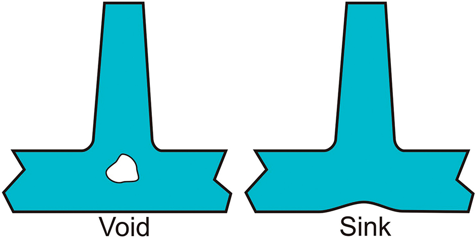
Figure 2.
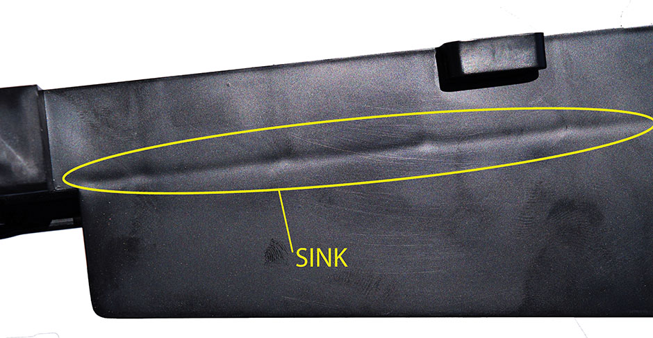
Figure 3.
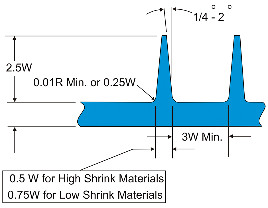
Figure 4.
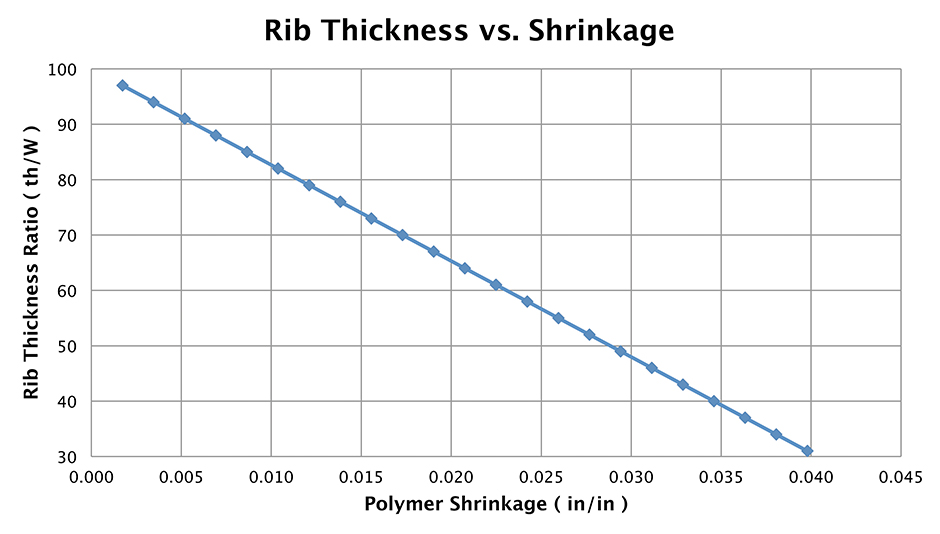
Figure 5.
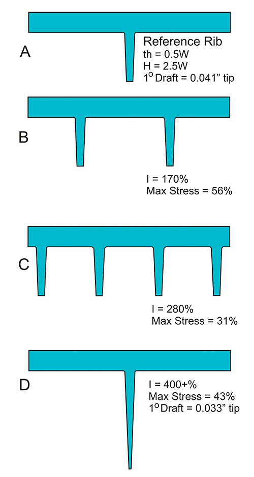
Figure 6.

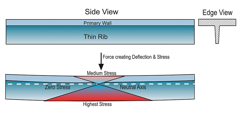
Figure 7.
Figure 7.
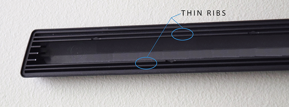
Figure 8a.
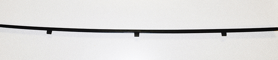
Figure 8b.
![]()
Have you had issues designing ribs into your parts?
Do you have any other injection molding-related technical questions for John? Please login to The Chain online forum and join the discussion in Tech Talk at: http://community.4spe.org/techtalk
At the risk of drawing the ire of 90%+ of plastic part designers, my experience is that by 90%+ of part designers create designs that fall far short of optimum. The problem is that most designers do not have the necessary foundational knowledge of the complex interdependency of their designs with the polymer, mold and injection molding process. For every part designer who doesn’t like reading this, I can find you a dozen molders who will cheer my position.
Simply stated – plastics and injection molding are complicated … and the interdependencies of the part design with these is much more complicated than most designers realize. Evidence of the degree of complexity is the fact that after nearly 150 years since the first molding machine, and more than 40 years developing state-of-the-art injection molding simulation, we still spend countless dollars on product start-ups and on debugging products and tooling.
The root of many design evils
The source of many molding problems is that the designer is following commonly accepted plastic part design guidelines.
Several decades ago, plastic part design “guidelines” began to emerge that tried to address some of the more obvious problems in producing injection molded plastic parts. Variations and evolutions of these appear in nearly every plastic part design book, guide or reference. Unfortunately, these guidelines often address one issue while creating another. The problem starts with part designers who follow these guidelines without understanding such consequences. Without full knowledge of the interaction of their part design with the mold, process and polymer, they cannot go through a critical thought process to apply more strategic approaches to their designs.
Fundamental and common to all plastic part design guidelines is the plea that the designer should maintain a constant wall thickness throughout a plastic part that is to be injection molded. This is considered the “cardinal rule” and is intended to help address mold filling, packing, shrinkage, residual stress and warpage issues. In particular, it is known that variations in wall thickness will create variations in shrinkage, which in turn creates residual stresses, which in turn can cause undesirable warpage in a plastic part, along with premature stress- and dimensional-stability-related failures.
So in a perfect world, all plastic parts would be produced with a constant wall thickness. The reality is that for many reasons this rarely can actually happen.
Breaking the cardinal rule
In this article we are going to limit the discussion of part design to the use of ribs on injection molded plastic parts. Ribs and gussets are features that generally are added to the primary wall of a plastic part for structural purposes. This could be to help the part resist deflection under load or to resist warpage. When adding ribs to the primary wall, the plastics designer must always consider manufacturability issues. These include consideration of part ejection, venting of air during mold filling, cooling and effects on mold filling and packing.
To this end, commonly applied design guidelines emerged decades ago that are widely practiced today. Many of these guidelines are for when the cardinal rule of maintaining a constant wall thickness should or must be broken.
Rib design guidelines
The following are commonly applied design guidelines for ribs and the logic behind these guidelines.
- Reduce the thickness of the rib relative to the primary wall: The intersection of the rib to the primary wall creates an increased volume (region ‘A’ in Fig. 1). This is compounded by the need to radius the intersection of the rib to the primary wall to minimize stresses. The increased volume at this intersection is generally filled by material flowing through the primary wall (region ‘B’ in Fig. 1).
During the compensation phase (commonly referred to as packing or second stage) of the molding process, the thinner primary wall will freeze first and thereby block compensating flow to the still shrinking region ‘A’. This will cause sinks and/or voids to form in this region. (See Fig. 2).
Figure 3 is a photo of sinks on the surface of a molded part. The sinks result from ribs on the opposite side. To address these problems, ribs are normally thinned relative to the primary wall. The thinner rib will reduce the volume at ‘A’ (Figure 2) and therefore reduce the localized shrinkage there. As this is a shrinkage issue, the logic is that the higher the shrinkage characteristics of a given polymer, the thinner the rib should be.
Figure 4 illustrates commonly used rib design guidelines. The thickness of the rib at its projected intersection with the primary wall is shown to be 50 to 75% of the primary wall’s thickness depending on a material’s shrinkage characteristics. High-shrink materials are normally considered those with shrinkages of more than 0.015 in./in. (most neat, semicrystalline materials are considered high-shrink materials). Low-shrink materials are those with shrinkages less than 0.008 in./in. (most amorphous materials and filled materials are low-shrink materials). As shrinkages can vary from less than 0.001 in./in. to more than 0.05 in./in., the designer must make judgments as to how to apply these guidelines. There is no hard rule that will work in all cases. In highly cosmetic parts that are particularly sensitive to sinks I have seen ribs used that are as thin as 30% of the primary wall. This might include parts that have a high gloss surface or are to be chrome plated.
As these rib thickness guidelines are based on shrinkage, you might consider using the graph (Figure 5). Note that following this graph or any guideline will not ensure that you will reduce the sink at the surface of the part to specification. Other factors such as material modulus, its thermal properties, mold cooling and molding process can also influence sinks.
- Radius the base of the rib: The base of the rib, where it intersects the primary wall, should have a radius. The size of the radius should be approximately 0.25 times the primary wall thickness with a minimum radius of 0.010 inch.
- Minimize the height of the rib: From a manufacturing standpoint, the ribs should be kept as short as possible and be drafted, i.e., tapered on both sides. Ideally the height of ribs should not exceed 2.5 times the thickness of the primary wall. Draft angles can range from less than 0.5° to as much as 2°, with 0.5° to 1° most commonly used. Shorter ribs and draft help minimize ejection problems. They also reduce potential for mold filling problems that might develop in taller thinned ribs. A shorter rib also will reduce the potential for excessive thinning of the rib tip resulting from the required draft (see Figure 6D). If increased rigidity is required, several short ribs are preferred to one tall rib. If multiple ribs are used, they should be spaced no closer than their height. This will help accommodate cooling at the base of the ribs.
Figure 6A shows the side view of a reference rib attached to a wall that is 1” wide and 0.100” thick (Wall thickness = W, Rib thickness = th, Rib height = H). The rib thickness follows the guidelines for a high-shrink material (0.5W) and has a 1° draft per side. Note this draft reduces the thickness at the tip of the rib to 0.041 inch. Three alternate rib design strategies are shown to increase the rigidity of the structure. The approximate increase in the moment of inertia (I) of these alternate designs is shown (I is the measure of the structure’s rigidity). Also shown is the maximum stress experienced in each of these ribs relative to the reference rib that would develop under load vs. the reference. (Design B would reduce maximum stress to 56%, Design C to 31% and Design D to 43% of the stress experience in the reference design.)
The design (“D”) at the very bottom of the graphic below has all the same attributes as the reference rib (“A”), except that it is twice as tall. The two designs (“B” and “C”) shown immediately below the reference rib have all the same attributes of the reference rib except the number of ribs has been increased. The logic for multiple ribs vs. taller ribs includes the concern of the rib tip becoming too thin. In this case note that the 1° draft on this taller rib results in its free edge thickness being reduced to 0.033 inch. Also, there is the increased potential for mold filling problems. Additionally, as the rib is taller it would be desirable to increase the draft angle; however, if it is increased, the thickness of the tip of the rib will quickly go to zero.
Figure 7 illustrates the stress distribution through a rib under flexural loading. It can be seen that the greatest stress is at the free edge of a rib. As this edge experiences the highest stresses when under load, it is important that it is not thinned too much. Additionally note the location of the Neutral Axis under a flexural load. This is where stress is zero. This zero-stress location is very close to where a void would be located. Therefore, in application, a flexed part is most likely to fail at the tip of the rib rather than due to a void located in the relatively low-stress location at the base of the rib.
Doing it right, but wrong
There are a number of issues with these commonly used design guidelines presented above. The first, and most troublesome is that thinning ribs create a variation in wall thickness that will create residual stresses and often causes a part to warp. So while attempting to address one issue (sinks and voids), thinning ribs become the source of another. The problem results from the fact that the thicker primary wall will take longer to cool and will shrink more than the thinner rib.
As a result of this variation in shrinkage, the part will tend to warp away from the rib. The warpage problem is compounded with high-shrink, semicrystalline materials. Remember that common design guidelines specify that to minimize sinks and voids with high-shrink materials, the rib should be thinned by 50% or more relative to the primary wall (see Figure 4). This thinner rib compounds warpage potential. Sinks vs. stress and warp are highly competitive objectives.
Ribs added to flat plastic parts to add rigidity with the intent to minimize warpage normally will have the opposite effect. In Figure 8, note that the thin ribs (top photo) are approximately 40% of the primary wall thickness. The resultant warpage can be seen from the side view of this 44-inch-long, automotive trim piece (bottom photo), where the part is warping away from the ribs that are on the bottom surface. The designer here followed common design guidelines specifying thin ribs to minimize the potential of any sinks on the show surface of this part. However, not knowing the consequences, the thin ribs caused the part warpage shown. More recent designs are more strategically designed to eliminate these ribs in order to minimize warpage.
In designing a plastic part, a designer must be sensitive to both the application and aesthetic issues related to the part. If cosmetics are not a concern, reducing the rib thickness becomes less important. A sink resulting from a thicker rib will have virtually no negative structural consequences. Voids also may be tolerated in many parts when they occur near the intersection of the rib to the primary wall. As noted earlier, this region sees minimal stress under flexural loads.
A second issue I will point out is the aversion to using taller ribs. This results in the recommendation to use more short ribs rather than a tall rib. Yes, the reasons for use of short ribs vs. taller ribs are good ones. However, if we explore this further we would find that a single 0.4-inch-tall rib would provide nearly the same rigidity as four of the shorter 0.25-inch-tall ribs shown in Figure 6. In this example, the four ribs would increase part volume by nearly 125% (rib volume by nearly 250%). Further, does a 0.40-inch-tall rib really create the manufacturability problems discussed earlier? Is the tip actually too thin given that the maximum stress is lower? Will it create a cavity filling problem? Will ejection be an issue? Will it increase or decrease the potential of warpage?
Material considerations
In addition to designing the rib considering the shrinkage characteristics of the material, one should consider the modulus, or rigidity, of the material. A sink is formed when the frozen material on the surface of the part is drawn inward as the material between the surfaces shrinks. A low-modulus material will be drawn in more easily by the shrinking material. With a high-modulus material, the frozen, high-modulus skin will better resist being pulled inward. As a result, the high-modulus material is more likely to form a void and the visibility of a sink minimized.
Other factors to weigh
If the material being molded is to be foamed, then ribs do not need to be thinned. The foaming action will pack the region at the intersection of the rib and primary wall. This is true of both chemical blowing agents or with specialty processes such as Trexel Inc.’s MuCell® microcellular foam injection molding technology.
When designing a plastic part, try to avoid the use of ribs. If the consequences are understood, often a more strategic design of the part can achieve the structural requirements without use of ribs. Additionally, some part shapes will be able to resist the stresses developed from the wall thickness variations of thin ribs — for example, a tube with longitudinal fins, or a bowl with internal cross ribs. There are also some part and tooling design, gating and process techniques that can be applied to help address this contrast (though these are all beyond the limits of this article).
Design guidelines for ribs are broken all the time with parts still being successfully molded. However, a designer should be aware of the potential problems created and be prepared to address them.
How should you design ribs?
When considering the challenges that face the injection molding industry and plastic part design, I often reflect on the comments of an old combat veteran who stated, “I survived by keeping my eyes open, knowing my surroundings, adapting to them and striving not to become numb with time to the threats around me.”
I find the same survival strategy to be appropriate to those involved in industry. For a plastic part designer:
- Keep your eyes open. Seek an understanding and be knowledgeable about things that surround your design. Clearly understand the purpose and logic of the older, art-based design guidelines. They can provide good value. However, don’t follow these blindly.
- Adapt your design and be creative from a position of knowledge. Consider the purpose vs. the consequences of using a design guideline. If cosmetics are a priority and you understand the threat of residual stresses and warpage, then judge the degree of the threat. Consider the limits of these design guidelines and their relationship to the polymer’s characteristics and the consequential demands on tooling and process. Be creative and adapt. Is there an alternate design approach that can provide the required structure without ribs, or a structure that can resist the stress resulting from the thinned rib? If others resist your revisions, argue for the revisions from a position of knowledge. Recognize and clearly point out the threats to others. Don’t limit your design to being simply a mechanical piece.
- Don’t become numb in the ways things are done today, including what is considered state-of-the-art. State-of-the-art can be a trap if it’s not recognized for what it is, which is simply the state of the way things are done today. If you are content with how things are done today, then you have already embraced Brer Rabbit’s tar baby.
You can’t advance without moving forward. Possibly it’s time for a journey.
ABOUT THE AUTHOR
 John Beaumont is president of the American Injection Molding Institute (www.aim.institute) and of Beaumont Technologies (www.beaumontinc.com), both of which are located in Erie, Pa. The primary mission of the AIM Institute is to help advance the injection molding industry by providing high-level educational programs to practicing professionals. Contact: beaumont@aim.institute