Sophisticated Software is Helping to Reshape Plastic Part Design
From optimization to simulation, digital tools are helping the cause
Previous Article Next Article
By Geoff Giordano
Sophisticated Software is Helping to Reshape Plastic Part Design
From optimization to simulation, digital tools are helping the cause
Previous Article Next Article
By Geoff Giordano
Sophisticated Software is Helping to Reshape Plastic Part Design
From optimization to simulation, digital tools are helping the cause
Previous Article Next Article
By Geoff Giordano
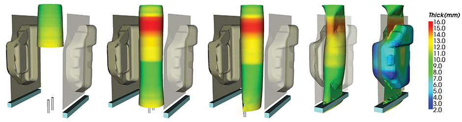
An extrusion blow molding simulation using BlowView. Most of the world’s plastic fuel tanks are designed using BlowView software, according to the National Research Council of Canada. The software simulates, among other things, proper thickness throughout the part. Image courtesy of BlowView
An extrusion blow molding simulation using BlowView. Most of the world’s plastic fuel tanks are designed using BlowView software, according to the National Research Council of Canada. The software simulates, among other things, proper thickness throughout the part. Image courtesy of BlowView
An extrusion blow molding simulation using BlowView. Most of the world’s plastic fuel tanks are designed using BlowView software, according to the National Research Council of Canada. The software simulates, among other things, proper thickness throughout the part. Image courtesy of BlowView
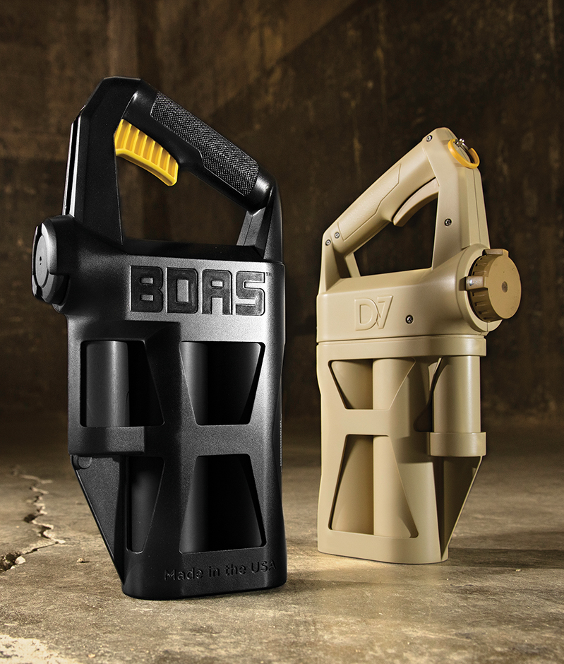
Bresslergroup and its vendors used SolidWorks to produce this multiresin biological emergency response device that sprays a mixture of chemicals to neutralize germs, viruses and bacteria. Photo courtesy of Bresslergroup
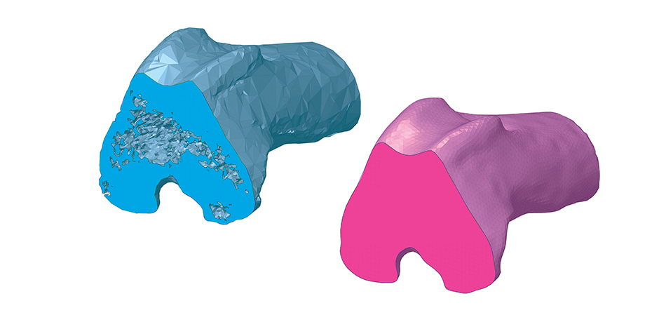
SpaceClaim’s shrink-wrap tool will solidify noisy STL files while normalizing facet size. Image courtesy of SpaceClaim 3D
Shrink wapping used to bridge small gaps between components, where unprintable objects now print as one complete part. Image courtesy of SpaceClaim 3D
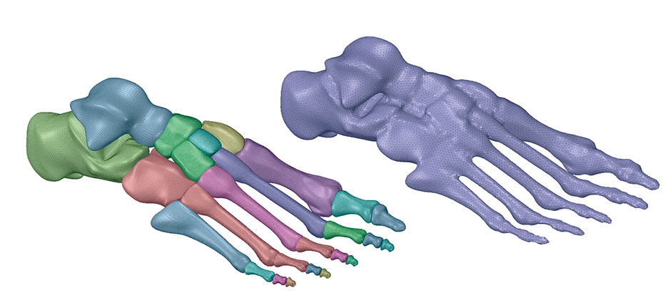
Highly organic STL shapes converted to a surface/CAD file with one simplified tool. Image courtesy of SpaceClaim 3D

Cutting-edge software is more vital than ever in the efficient production of top-quality plastic products, from fuel tanks to more complex products.
Whether it’s industry standard SolidWorks, or something more niche like the BlowView simulation software created by the National Research Council Canada, design software for plastics is ever-evolving.
A Solid Foundation
According to the website for Dassault Systèmes’ SolidWorks, one in 400 working Americans is using its software. And now, the product includes the plastic simulation capability from its Simulia brand.
“We are continuously enhancing the user experience … to help plastic part designers, manufacturers and mold makers optimize the cycle from design to manufacturing,” says Lotfi Derbal, senior product portfolio manager for SolidWorks.
To facilitate simulation-driven design for plastics part production, SolidWorks Plastics runs inside SolidWorks, he said. “That means no data translation issues, and users do not have to learn how to use another interface.” SolidWorks lets designers create models and meshes in familiar environments, then analyze their work. “It helps users synchronize design changes and validate product designs more efficiently in the early design phase.”
In fact, under a partnership with the University of Massachusetts Lowell, tests comparing simulations to actual parts demonstrated simulation accuracy greater than 95 percent, he says.
An industry mainstay since its introduction in 1995, SolidWorks remains geared to solving key concerns for plastics design engineers, Derbal explains:
- Will my part fill? Will there be air traps? Engineers need help identifying where to vent the mold. They need to be able identify short shots and optimize part geometry/process parameters accordingly.
- Does the part look good to the user, with no visible weld lines or sink marks? SolidWorks helps designers move injection locations to eliminate weld lines and optimize rib design to eliminate sink marks.
- Can I predict the final shape of the molded part? SolidWorks helps reduce component warpage due to imbalances in plastic part cooling, as well as evaluate design alternatives to minimize warpage.
Defusing Chemical Threats
When first-responders wanted a more efficient, immediately deployable spray device that releases a complex mix of chemicals to neutralize germs, viruses and bacteria, design consultancy Bresslergroup of Philadelphia used SolidWorks to fill the bill.
BDAS+ is a high-durability disposable, so it’s one-time use for potentially extreme conditions,” explained Mark Clark, lead mechanical engineer and senior program manager at Bresslergroup. “It’s also a portable product, so weight was a concern. We wanted to make it tough and durable, and we didn’t want to use any more material than was absolutely necessary.”
SolidWorks was used to assess the mass of parts throughout the process and optimize wall thickness. The software “offers a range of design-check tools that are valuable for identifying potential problems that may have been missed or overlooked,” Clark explains. “The draft check, thickness check and interference check were heavily used on this project and allowed for faster time to market by quickly identifying potential issues during the design process. We also did draft analysis and a considerable amount of finite element analysis (FEA) to check part stiffness and strength.”
While testing component FEA, he says, “we relied heavily on the SolidWorks Simulation. One short cut we used to speed up analysis was to cut out areas of the product that were not part of the analysis, allowing the analysis to run more efficiently. The symmetry feature in analysis helped us get feedback much faster.”
After optimizing a feature, “our main engineer on the project, Meggie Oudheusden, would run final FEA using the entire models to confirm that our shortcuts didn’t have any unintentional impacts. Wherever possible we verified the FEA with physical testing to confirm our assumptions.”
Geometry constraints, chemical resistance, recyclability and impact resistance made resin selection complicated, Clark notes. “We looked at different types of resins and measured their ultrasonic weldability against price, density and colorability. Our molding partner used SolidWorks, too, which let us exchange information back and forth during the design for manufacturing cycle with a high degree of fluidity.”
Ultimately, different polymers were chosen: a polypropylene blend for the safety pull tab, glass-reinforced polypropylene for the handle, and impact-modified polypropylene for the body.
Besides SolidWorks, “our industrial designers used Autodesk Sketchbook to create design sketches, Keyshot 3D rendering software for final design renderings, and The Foundry for animation development,” Clark says. “The engineering team also relied heavily on Excel and LabVIEW to run parameter optimization calculations and bench testing.”
Geometries Made Easy
When ANSYS acquired SpaceClaim 3D modeling software in 2014, it expanded a well-established portfolio. Since then, it has continuously upgraded the software.
“The biggest thing we’ve added is the 3D printing prep capability,” said John Graham, senior product marketing manager, which has expanded the software beyond its previous geometry-modification repertoire into the editing of STL (stereolithography) files. For example, a user can optimize an STL file for printing by adding a custom infill, or patch holes in a scan of a plastic injection mold in a matter of seconds.
“If you’re involved with topology optimization and you need to clean up STL files, this is an excellent tool,” he says. The Shrinkwrap feature, introduced less than a year ago, allows a user to smooth over “very dirty STL files.”
SpaceClaim “has always been about rapid geometry cleanup — taking complex [data] and making it simple,” Graham noted. Two years ago, “ANSYS had a CAD solution, but it mimicked [others in the industry]. If you want to do an accurate simulation and do it rapidly, having clean geometry is paramount. [ANSYS] realized SpaceClaim is very much a game changer.”
Not only does SpaceClaim clean up design geometry, it simplifies concept modeling and facilitates reverse engineering by extracting geometric data from complex shapes.
“It’s the Swiss Army knife of 3D,” says Graham, who used to be an applications engineer. And with its newest reverse-engineering tool, SpaceClaim is every bit as capable as alternatives costing four to five times more, he asserts.
Canada’s Simulation Solution
In the early 1990s, the National Research Council of Canada (NRC) began working with a group of companies in a consortium called SIGBlow (Special Interest Group in Blow Molding) to answer industry requests for a tool to simulate blow molding manufacturing. NRC’s BlowView software reflects the input and support of the consortium members. Now, most of the world’s plastic fuel tanks are designed using BlowView, the NRC says.
When this began, explains Project Manager Anna Bardetti, there were plenty of tools for injection molding but none for blow molding, which she calls more of an art. “Sometimes it’s difficult for the operator to set the right conditions on the blow molding machine.”
BlowView, a finite element software, is dedicated to blow molding, stretch blow molding, thermoforming and twin-sheet extrusion blow molding. “Everything in the interface is focused on blow molding, so it’s more user-friendly compared with generic software.” For instance, “when the users input their die design, our interface is configured to look like what the operators would see on their machine.”
Meeting at least twice a year, the consortium provides real-world input into upgrades of BlowView. “Typically, new versions are released regularly to address the latest technical advancements,” Bardetti says. “If it’s not new functionalities being added, then existing functionalities and features are being upgraded to reflect industry requirements.”
The NRC relies heavily on client input “to validate our material models and predicted thickness and warpage results. For extrusion parts, we’re trying to predict the shape of the parison being extruded to ensure the right thickness distribution. In the case of a generic part, the simulation could start with a parison of a given thickness from which we start incorporating various types of parison programming, depending on the type of the die, and then analyze the difference observed on the final thickness distribution of the part.”
More recently, the focus has been on warpage. “Once the part is formed”, said Bardetti, “we analyze the in-mold cooling, as well as the part cooling outside of the mold. As the part begins to warp, we compare our results to data that has been scanned from a part produced by our client’s machine, to confirm how accurately we’re able to predict warpage as it occurs.”
Primarily used by larger auto part manufacturers and consumer packaging companies in Canada and the U.S., BlowView also has users in Europe and Asia. Ford Motor Co., a consortium member for more than 20 years, has used BlowView to significantly reduce the weight of fuel tanks. Another automotive OEM used the software to resolve warping of the neck of a windshield washer reservoir.
To augment BlowView’s modeling repertoire, NRC is building in the capability to simulate 3D suction blow molding. “The materials and extrusion of the parison are the same,” Bardetti said, “but because (material is) sucked into the mold, there are dynamics going on between the air and the parison that we don’t have in conventional blow molding.”
NRC said it expects to release the first version of the Suction Blow Molding functionality by the end of this year.