A Fracture Mechanics Approach to Service Life Prediction of HDPE Fusion Joints in Nuclear Applications
Previous Article Next Article
By S. Kalyanam1, P. Krishnaswamy1, Y. Hioe1, D.J. Shim1, and E. Focht2
1Engineering Mechanics Corp. of Columbus (Emc2), Columbus, Ohio, USA
2United States Nuclear Regulatory Commission, Rockville, Maryland, USA

Ashish M. Sukhadia of Chevron Phillips Chemical Company LP (left) presented an ANTEC 2015 Best Paper Award to Prabhat Krishnaswamy of Emc2.
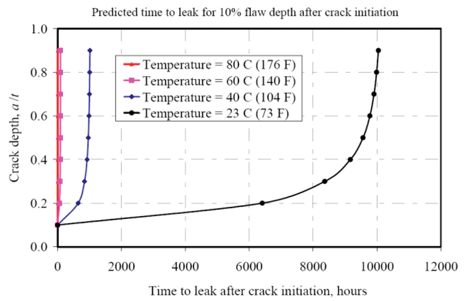
Figure 1: Effect of temperature on failure time due to SCG following crack initiation.
Nomenclature
BPV Boiler and Pressure Vessel
DR dimensional ratio (DR = OD/thickness)
FEA finite element analysis
HDPE high-density polyethylene
ID inner diameter of pipe
OD outer diameter of pipe
PE polyethylene
PENT Pennsylvania edge notch tension
SCG slow crack growth
SENT single edge notch tension
SIF stress intensity factor (KI)
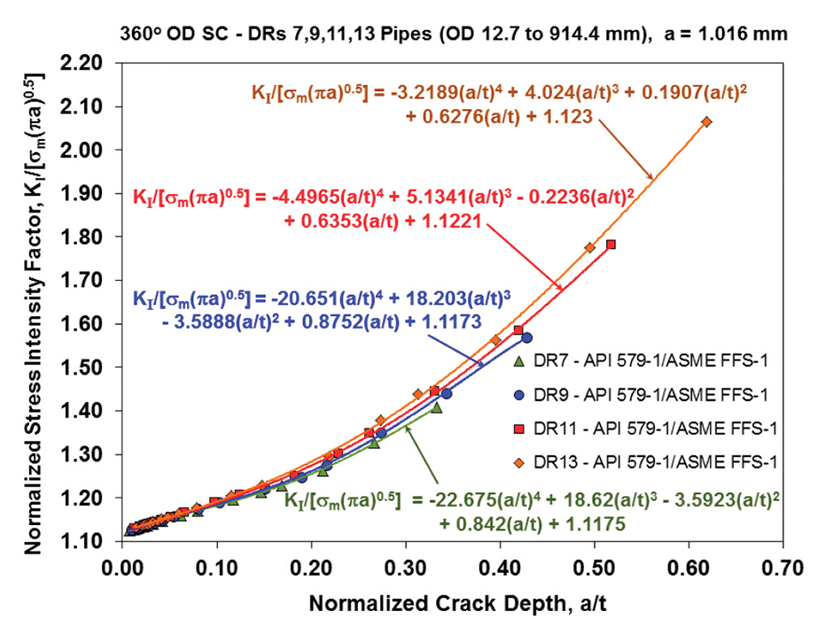
Figure 2: Normalized SIF for DR 7, 9, 11, and 13 pipes, with 12.7-mm (0.5-in.) to 914.4-mm (36-in.) OD containing full-circumference (360°) OD surface crack of 1.016 mm (0.04-in.) depth.
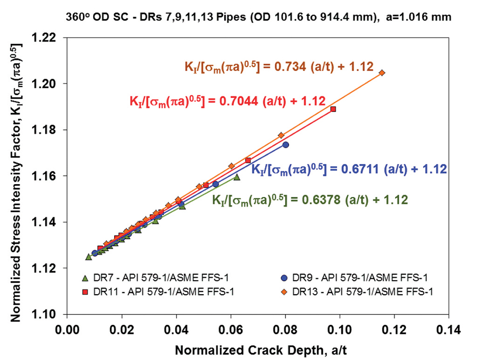
Figure 3: Normalized SIF, KI/σm(πa)0.5, for full-circumference (360°) OD surface crack of 1.016 mm (0.04 in.) depth on 101.6-mm (4-in.) to 914.4-mm (36-in.) pipes with DRs 7, 9, 11, and 13.
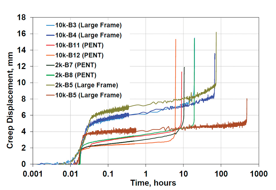
Figure 4: Creep displacement versus time from SENT and PENT tests on PE4710 bimodal HDPE pipe joints.
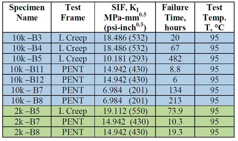
Table 1: SCG Tests on Butt-fusion Joint (“B”) Materials of PE4710 Bimodal HDPE 10,000 Hours PENT (“10k”) and 2,000 Hours PENT (“2k”) Resins
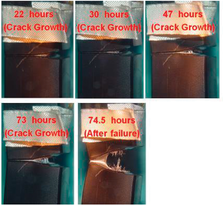
Figure 5: SCG in specimen “2k-B5” with notch in HDPE butt-fusion joint material, tested at 2.758 MPa and 95°C in large creep frame.
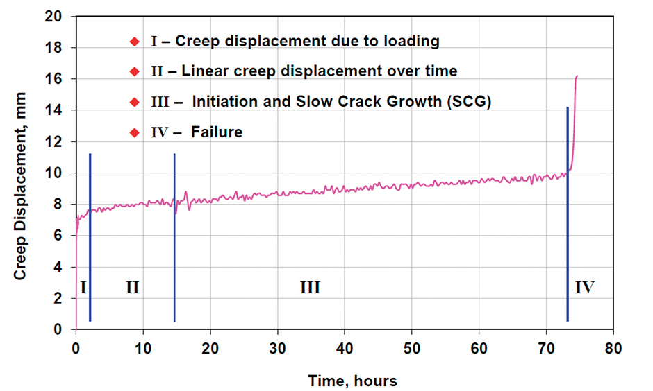
Figure 6: Displacement versus time for SCG specimen with notch in fusion material, tested at 2.758 MPa, 95°C, and ai/W = 0.25, with KI = 18.486 MPa-mm0.5.
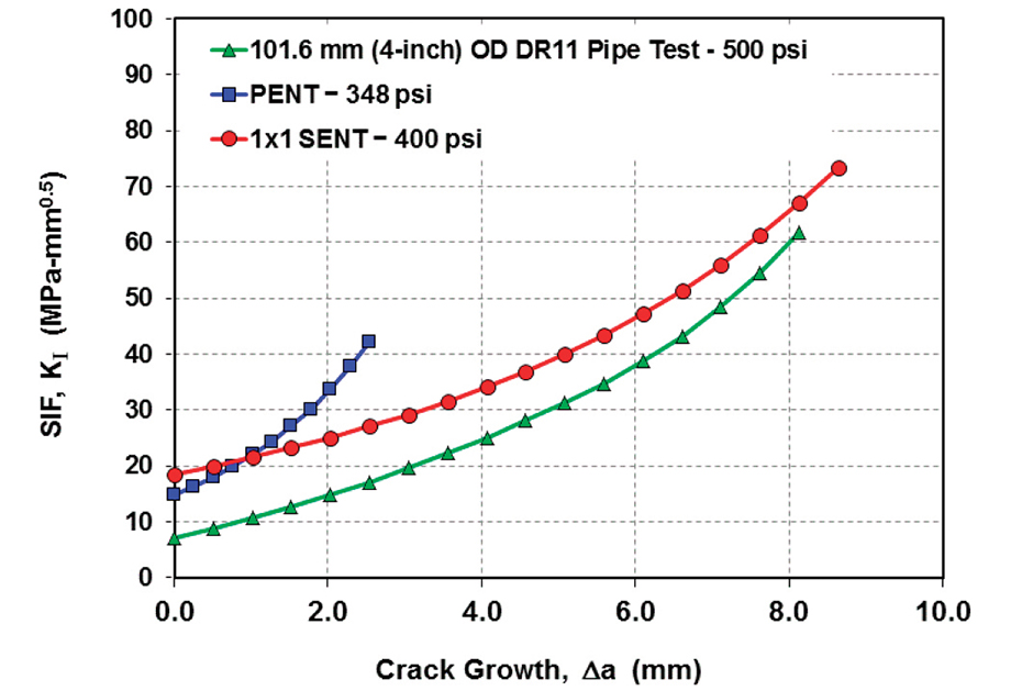
Figure 7: Effect of specimen width on the SCG and SIF with crack growth (Δa), and corresponding time to failure.

Note: This is an abridged version of the authors’ original ANTEC® Orlando 2015 paper, which won SPE’s Plastic Pipe and Fittings Special Interest Group’s Best Paper Award (this year sponsored by Chevron Phillips Chemical Company LP). To see the complete paper and the full ANTEC proceedings, contact SPE customer relations at +1 203-775-0471.
High-density polyethylene (HDPE) pipes are considered by the nuclear industry as a potential replacement option to currently employed metallic piping for service-water applications. The nuclear industry is motivated in using HDPE in service water piping due to inherent advantages such as resistance to corrosion, abrasion resistance, much lower weight compared to steel, high flexibility, ductility and resistance to soil movement, and superior flow characteristics due to hydraulic friction.
More recently, higher-grade HDPE materials (such as PE100 in Europe and Asia and PE4710 which meets the cell class 445574C as per ASTM D33501) have become candidate materials for safety-related nuclear service water applications, high-pressure gas transmission, and other hydraulic/water distribution applications. HDPE piping has been installed in the Callaway and Catawba plants with relief requests.2,3 HDPE piping and fusion-joints are being evaluated from the perspective of design, operation, and service life before their routine installation in nuclear power plants.
Past data on safety-related applications for PE piping in the gas distribution industry were developed for smaller diameter pipes (203.2 mm (8 in.) or less) that are buried and operate at temperatures that are around 22.8°C, which is much lower than service water application temperatures (60°C). It is well known that the major failure mode of concern in HDPE piping is slow crack growth (SCG) that occurs from flaws under sustained stresses.4
SCG rates in PE materials vary exponentially with temperature, specified by:
da/dt = AKn exp(Q/RT) Equation 1
where da/dt is the SCG rate, K is the stress intensity factor, T is the temperature, R is the universal gas constant, and A, n, and Q are material constants. Equation 1 depicts the SCG rate after initiation and does not include the “time to initiate” or the time under the sustained load prior to crack initiation.
Using Equation 1 and material constants that are available in the literature,5,6 the case of a circumferential, semi-elliptical surface crack in a 24-in. (610-mm) DR-11 pipe subjected to 2.758-MPa internal pressure was analyzed at four different temperatures.7 The results in Figure 1 show that the predicted time to failure after crack initiation decreases exponentially with temperature, being 10,000 hours at 22.8°C and 10.9 hours at 80°C. It was hence required to investigate the SCG resistance of HDPE at these high service temperatures using coupon (single edge notch tension (SENT) and Pennsylvania edge notch tension (PENT)) testing and NPT [notched pipe testing].
The higher operating temperatures of safety-related piping in nuclear power plants of up to 60°C requires the evaluation of the SCG resistance of both the parent and joint materials in the pipe. Confirmatory studies were conducted between 2007 and 2012 to understand the issues related to the structural integrity, critical flaw size, and material resistance of parent PE4710 HDPE materials.8,9,10 The critical design basis in Code Case N-755 Revision 1 defines the allowable stresses in Class 3 PE piping to be 3.45 MPa at 60°C. In addition, any scratch/indentation (surface flaw) that is less than or equal to 10% of wall thickness or 0.040 in. (1.0 mm), whichever is smaller, is acceptable for the parent pipe material. The reason for flaw acceptance criteria has been discussed in recent articles, where it was shown that the stress intensity factor (SIF (KI)) could vary significantly for the same flaw aspect ratio, when various diameters and thickness of HDPE pipes are considered.11,12
Experimental investigations have revealed that there is a marked difference in the time to failure when the notch/flaw is in the butt-fusion joint, as opposed to when the notch/flaw is located in the parent unimodal or bimodal PE4710 HDPE material.9,13 An unresolved concern is the effect of the fusion process on the integrity of the joint, specifically, if there are flaws in the fusion area. The potential impact of flaws in the fusion joint on the service life of the HDPE piping is being evaluated. The findings from research on the critical flaw size evaluations by the nuclear industry and regulators are presented to the ASME Boiler and Pressure Vessel (BPV) Code Committees.
This paper discusses the following three aspects related to the structural integrity of butt-fusion HDPE pipe joints:
- Mathematical description of the driving force, SIF (KI) for SCG: Stress intensity factors for circumferential flaws (elliptical, 360°) and embedded flaws akin to lack-of-fusion zones in plastic pipes with diameters ranging from 101.6 mm (4 in.) through 914.4 mm (36 in.) and dimensional ratios (DRs) from 7 through 13.
- Characterization of SCG resistance of HDPE fusion joints: SCG tests using SENT, PENT, and whole-pipe tensile specimens with a flaw/crack in butt-fusion joints under sustained load and temperature.
- Selection of reliable service life prediction model: Selecting appropriate models used to translate the coupon test (SENT, PENT) data to predict the failure time in whole pipe tensile and service water nuclear piping and their validation.
Mathematical Description of Driving Force
It is important to understand the range of SIF arising in surface flaws from lack-of-fusion or other causes (e.g., joint misalignment, joint contamination, improper heat/soak time) during the butt-fusion joining of HDPE pipes.14
SIF was computed using API 579-1/ASME FFS-1 handbook15 solutions for semi-elliptical surface cracks (crack length/depth, 2c/a = 5 and 10) and full-circumference (360°) OD surface cracks in a 914.4-mm (36-in.) DR9 pipe. For the case of the OD surface crack, internal pressure (500 psi (3.5 MPa)), crack face pressure, and corresponding end-cap loading were applied. The SIF difference between a surface crack with 2c/a = 10 and 2c/a = 2199 (360°) was found to be about 6%. Hence the full-circumference (360°) was chosen as the limiting/conservative surface crack for developing SIF variations for all OD surface cracks. From a material standpoint, this is also representative of an equivalent crack that arises from several lack-of-fusion zones or flaws that could potentially bridge to form one long crack.
Figure 2 shows the normalized SIF, KI/σm(πa)0.5 determined for a 1.016-mm (0.04-in.) deep full-circumference OD surface crack in pipes with diameters ranging from 12.7 mm (0.5 in.) to 914.4 mm (36 in.) and DRs ranging from 7 to 13. The geometric factor, F = KI/[σm(πa)0.5] was found to be nonlinear in the range from a/t = 0.01 to 0.5. However, for the nuclear power plant piping, HDPE pipes with OD of 101.6 mm (4 in.) to 914.4 mm (36 in.) are most relevant, and were hence considered in the development of average empirical equations for SIF. Figure 2 shows that a linear fit could represent well the values of F = KI/[σm(πa)0.5] in the range of a/t from 0.01 to 0.12.
SIF values for various DRs (7, 9, 11, and 13) were obtained for full-circumference OD surface cracks. Using the API 579-1/ASME FFS-1 SIF handbook15 solutions (see Figure 3), a simplified SIF Equation 2 has been developed for whole pipe tensile testing with a full-circumference OD surface crack under internal pressure and corresponding axial load:
KI = σm(πa)1/2 [1.12 + 0.6868(a/t)] Equation 2
where σm is the nominal axial membrane stress, a is the flaw depth, and t is the wall thickness of the pipe. However, for an accurate SIF solution for each of the DRs of HDPE pipe considered, the individual SIF relations shown in Figure 3 could be used.
Equation 2 for SIF was developed along the same lines as those developed for a semi-elliptical and infinitely long axial surface crack on the pipe OD subjected to internal pressure loading.11 Details of this simplified relation for calculating SIF was presented at the recent ASME BPV meetings in February 2014.16
While an earlier solution provided by Grebner17 spans a larger a/t (0.1 to 0.9) from finite element analysis (FEA) similar to the results shown in Figure 2, the solution presented here is tailored for the range of allowable flaws in HDPE pipes and hence more accurate within this range. The developed simplified SIF relation shown in Equation 2 was compared with Grebner’s solution, Equation 3:
KI = σ(πa)1/2 [A0 + A1λ + A2λ2 + A3λ3+ A4λ4] Equation 3
where λ = a/t, A0 = 1.2114378, A1 = -1.6577755, A2 = 11.743555, A3 = -16.672913, and A4 = 9.7708125.
Characterization of SCG in HDPE Joints
HDPE joints fabricated by a supplier qualified for nuclear applications were used in this study. The resins for the pipes have been called “10k” and”2k,” corresponding to their 10,000-hour and 2000-hour PENT resin failure times.
The service life prediction models employ the failure time from a PENT, SENT, or SENB [single edge notch bending]18 test to obtain the performance life of HDPE pipe with a detected flaw depth, operating temperature, and pressure. Recent work indicates that the PENT and SENT specimens have an SIF and constraint/transverse T-stress (coefficient β = [T(πa)0.5]/KI) that is close to that of a surface crack in an HDPE pipe and have been the focus of recent investigations.9,13,19
PENT and SENT tests were conducted with the initial razor-sharpened crack inserted in the butt-fusion joint material. To determine the variability of failure times and validate service model predictions, tests were conducted at PENT KI = 14.942 MPa-mm0.5 and SENT at KI = 18.486 MPa-mm0.5 and 10.181 MPa-mm0.5. Figure 4 shows the creep displacement versus time for PENT and SENT specimens prepared with a notch in the butt-fusion joint material of HDPE pipes. The butt-fusion joints were made using 10k and 2k PE4710 bimodal HDPE resins9,13 as per ASME Code Case N-755 and TR-33.20
Comparison of parent material SCG failure time (7893 hours when tested at 95°C and KI =18.486 MPa-mm0.5) with the butt-fusion joint material SCG failure time (less than 100 hours when tested at 95°C and KI =18.486 MPa-mm0.5) were discussed in an earlier work.9 From recent SENT test data shown in Figure 4 for specimen “10k-B5,” the SCG in fusion joint material shows an order of magnitude smaller failure time at 95°C, even under a much lower KI of 10.181 MPa-mm0.5.
Table 1 shows the butt-fusion joint SENT and PENT specimens tested to date from 10k and 2k PE4710 HDPE resins and their corresponding failure times. Details on the calculated SIF using FEA, comparison of the two test frames (“L Creep” and “PENT”), and the layout for extraction of these specimens from a 12-in. (305-mm) DR11 HDPE pipe can be found in an earlier work.9
Figure 5 shows the SCG and failure images from a bimodal HDPE joint material (PE4710, 2k resin) tested at 95°C and at a SIF of 18.486 MPa-mm0.5. Figure 6 shows the creep displacement versus time, which indicates a small initial nonlinear displacement when the specimen is loaded (time, “I,” < 2 hours), followed by damage development (t < 15 hours), and a rather constant displacement versus time slope during SCG for about 59 hours (15 < t < 73.9 hours), before final failure at 73.9 hours. The test indicates the small time required for damage development in the butt-fusion joint material. Markedly lower joint material SCG failure times were also observed in work by other researchers on PE resins,21 PE resins used in gas pipelines,18 and our earlier study on unimodal HDPE resins.13
Similar observations were made from creep displacement versus time recorded and photos depicting the damage development and SCG in recently tested butt-fusion joint material specimens at a much lower SIF of 10.181 MPa-mm0.5.
Another important aspect noticed from SCG tests on parent and butt-fusion joint materials was that the time to failure comprises: (i) time to initiation of crack growth (ti) (sometimes referred to as “incubation time”) and (ii) time for the SCG (tg). When comparing the PENT (B = 25 mm, Width, W = 10 mm, ai/W = 0.35), SENT (B = 25.4 mm, W = 25.4 mm, ai/W = 0.25), and hydrostatic tests (e.g., 101.6-mm DR11 pipe with W = 10.42 mm, ai/W = 0.10), the remaining ligament length (W-ai) may be different for each of the test specimens.
Figure 7 shows that for the same amount of crack growth/extension (Δa), the variations of SIF with crack growth in the PENT and SENT and whole-pipe tensile specimens are different. Although the final/total time to failure has been used to translate the information between various HDPE SCG tests (PENT, SENT, and hydrostatic/NPT) by researchers worldwide, it is necessary to develop a more detailed understanding of time for crack initiation (ti), crack growth (tg), and time for failure (tf = ti + tg).
From earlier investigations9 it was found that the SCG test failure time using SENT tests on parent material could be correlated to the 10k or 2k PENT failures on the compounded resin materials. However, from Figure 4 (or Table 1) it was observed that the butt-fusion joint failure times are similar, irrespective of the parent material. More tests at various SIF and temperatures and a broader array of fusion joints are required to gain a better understanding on the impact of (i) fusion process and parameters and (ii) parent pipe material resin PENT failure time on butt-fusion joint failure times.
Acknowledgements
This work has been supported by the U.S. Nuclear Regulatory Commission (NRC), Office of Research. The authors wish to acknowledge NRC-RES Program Manager Eric Focht and Josh Kusnick for their support and input for this effort. The authors also wish to acknowledge the support of Emc2 staff George Wall, Brian Tosi, Russell Hattery, and Paul Mincer for the experimental work.
References
- ASTM D3350-12, “Standard Specification for Polyethylene Plastic Pipe and Fittings Materials,” 2012.
- US NRC Relief Request documents for Ameren’s Callaway Plant, ADAMS Accession No. ML072550488 and ML082390955.
- US NRC Relief Request documents for Duke Energy’s Catawba Plant, ADAMS Accession No. ML063120215.
- D.A. McGee and others, “Service performance of polyethylene pipes containing surface notches subjected to internal pressure,” Final Report GRI-00/0137, Gas Research Institute, June 2000.
- C. Corleto, “Accelerated methods to determine or predict failure in polyethylenes,” Proceedings of Plastics Pipes XIII, Oct. 2006.
- C. Corleto, “Fundamental slow crack growth properties using instrumented PENT testing,” Proceedings of the 17th International Plastic Fuel Gas Pipe Symposium, Oct. 20-23, 2002.
- P. Krishnaswamy, E. Focht, D.-J. Shim, T. Zhang, “Use of polyethylene (PE) pipe in safety-related, Class 3, service-water piping,” Proceedings of 16th International Conference on Nuclear Engineering, ICONE 16, May 11-15, 2008, Orlando, Florida, USA.
- P. Krishnaswamy, E. Focht, D.-J. Shim, “Use of polyethylene pipe in safety-related nuclear power plant piping,” Plastic Pipes XIV, Sept. 22-24, 2008, Budapest, Hungary.
- S. Kalyanam, D.-J. Shim, P. Krishnaswamy, Y. Hioe, “Slow crack growth resistance of parent and joint materials from PE4710 piping for safety-related nuclear power plant piping, PVP 2011-57874, Proceedings of ASME 2011 PVP Conference, July 17-21, 2011, Baltimore, Maryland, USA.
- S. Kalyanam, P. Krishnaswamy, D.-J. Shim, Y. Hioe, E. Focht, “Structural Integrity of HDPE Piping and Joints in Nuclear Safety-Related Applications,” Proceedings of ASME ICONE2012 Conference, July 30-Aug. 3, Anaheim, California, USA.
- S. Kalyanam, P. Krishnaswamy, M. Uddin, D.-J. Shim, “A simplified stress intensity factor relation for assessment of external axial flawed safety-related nuclear power plant HDPE piping,” Proceedings of the ASME 2011 PVP Conference, July 17-21, 2011, Baltimore, Maryland, USA.
- P. Krishnaswamy, S. Kalyanam, Y. Hioe, D.-J. Shim, “A Methodology to Predict Critical Flaw Size in HDPE Piping and Joints in Nuclear Safety-Related Applications,” Plastic Pipes XVI, 2012.
- D.-J. Shim, P. Krishnaswamy, E. Focht, “Comparison of Parent and Butt Fusion Material Properties of High Density Polyethylene,” Proceedings of ASME 2009 Pressure Vessels and Piping Conference, July 26-30, 2009, Prague, Czech Republic.
- S. Crawford, S.R. Doctor, A.D. Cinson, M.W. Watts, T.L. Moran, M.T. Anderson, “Assessment of NDE Methods to Detect Lack of Fusion in HDPE Butt Fusion Joints,” Proceedings of the ASME 2011 PVP Conference, July 17-21, 2011, Baltimore, Maryland, USA.
- API 579-1/ASME FFS-1, Fitness-For-Service, Second Edition, June 2007.
- P. Krishnaswamy, “Development of Flaw Acceptance Criteria for Butt Fusion Joints in HDPE Piping – A Status Report,” ASME BPV Section XI, Task Group on Flaw Evaluation for HDPE Pipe, San Diego, Feb. 2014.
- 17.H. Grebner, “Finite Element Calculation of Stress Intensity Factors for Complete Circumferential Surface Cracks at the Outer Wall of a Pipe,” Intl. J. Frac., 27, R99-R102, 1985.
- C. Popelar and others, GRI Reports, The Ohio State University.
- EPRI Report 10225665, “Slow Crack Growth Testing of High-Density Polyethylene Pipe: 2011 Update,” Aug. 2011.
- TR-33, “Generic Butt-Fusion Joining Procedure for Field Joining of Polyethylene Pipe,” Plastics Pipe Institute, 2012.
- X. Lu, R. Qian, N. Brown, G. Buczala, “The Effect of Pressure and Contaminants on Slow Crack Growth in a Butt Fusion in a Polyethylene Gas Pipe,” J. Appl. Poly. Science, 46, 1417-1427, 1992.