Good Venting
It’s a key requirement for quality injection-molded parts— here’s how to achieve it
Previous Article Next Article
By Mark Rosen
Corex Design Group Inc., Franklin Lakes, New Jersey, USA
Good Venting
It’s a key requirement for quality injection-molded parts— here’s how to achieve it
Previous Article Next Article
By Mark Rosen
Corex Design Group Inc., Franklin Lakes, New Jersey, USA
Good Venting
It’s a key requirement for quality injection-molded parts— here’s how to achieve it
Previous Article Next Article
By Mark Rosen
Corex Design Group Inc., Franklin Lakes, New Jersey, USA
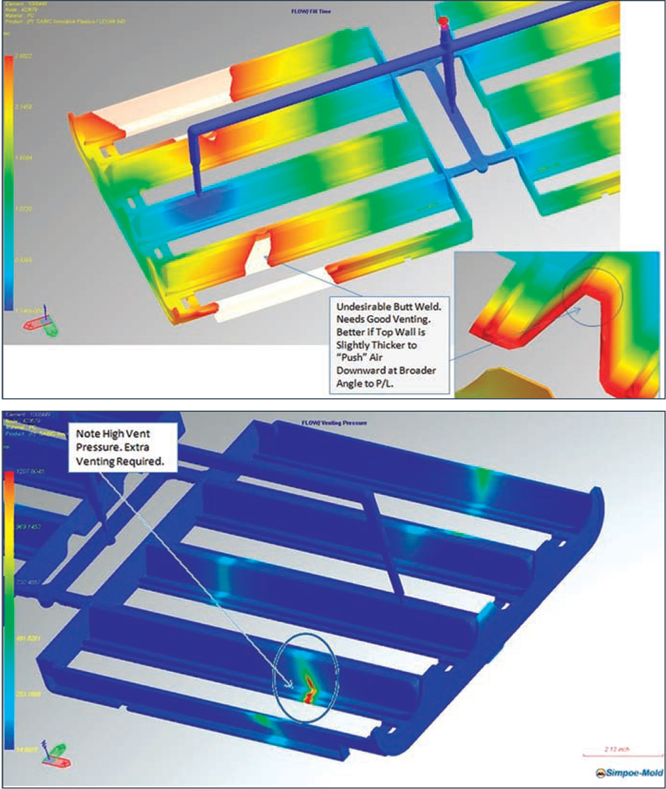
Figure 1: Flow front with a bad weld (top image); high pressure at weld site (bottom) with likely a slower fill time required to avoid burn marks.
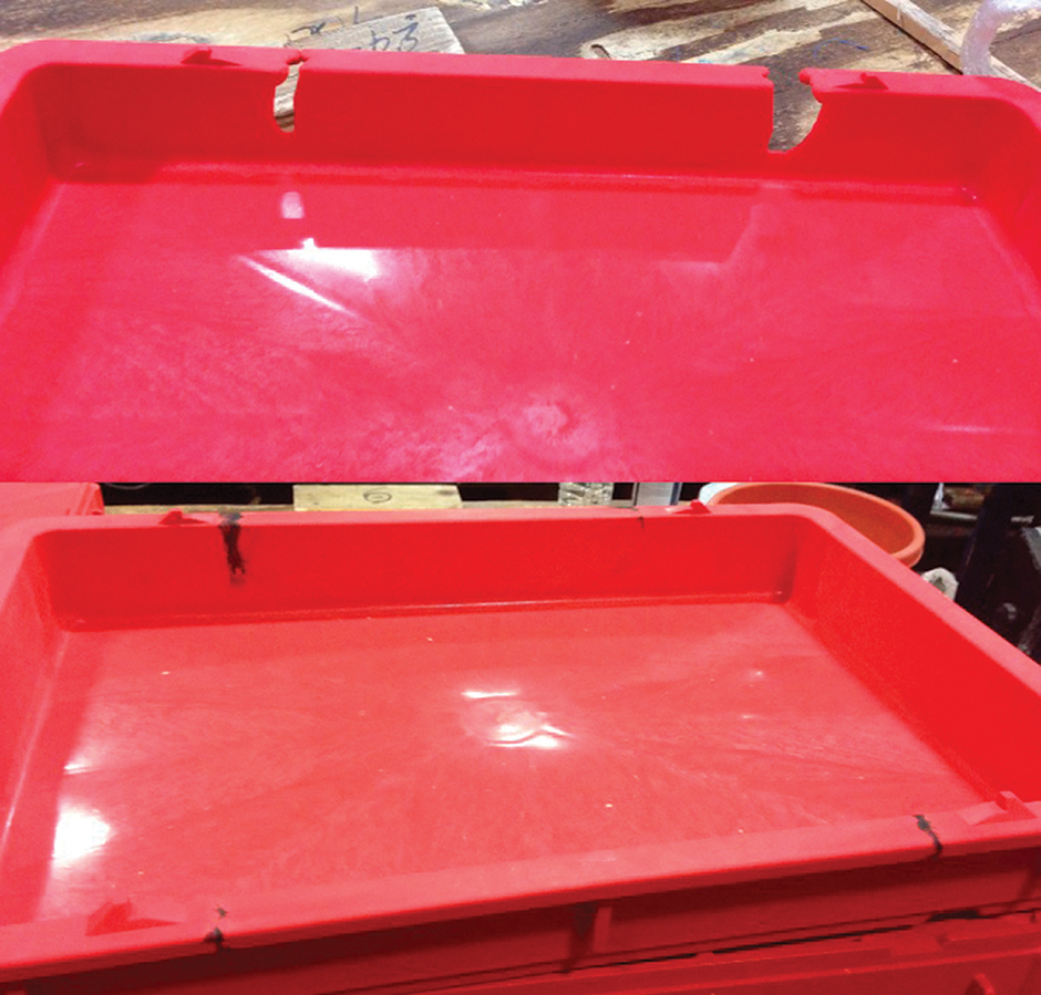
Figure 2: Venting issues in molding a large tote: a short-shot with a gas trap at end of fill (top half of image) and resulting burn marks on part (bottom).
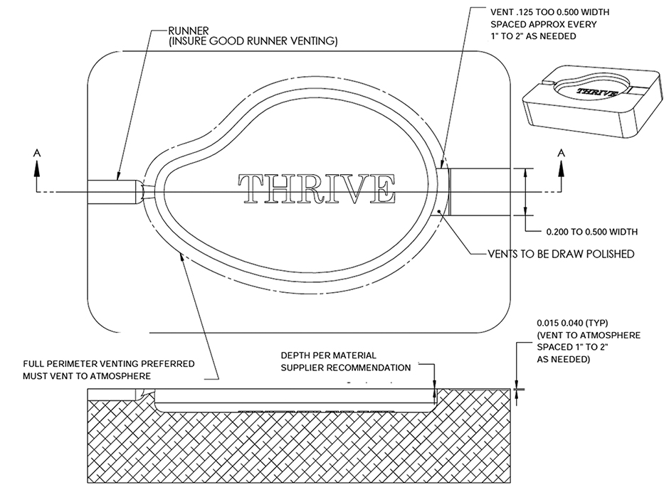
Figure 3: Venting recommendations (image courtesy of Weyerhaeuser).
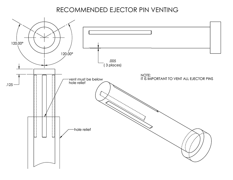
Figure 4: Ejector pin venting recommendations.
Processing Conditions: Techniques to Aid Venting
- When setting temperatures, the preferred situation is to use a lower melt temperature and, if needed, raise the mold temperature. The primary reason for this is the vents run cleaner at the lower melt temperatures due to less separation of the lower-molecular weight additives (see the “How Does Venting Relate to Material Selection?” section in the main article). Of course, this also allows for faster cycle times.
- For difficult-to-vent molds, try to use two-stage injection profiles to slow down the flow front at the end of fill.
- Set the screw RPM so screw recovery time is, ideally, around 80% of cooling time. Longer soak times can result in higher amounts of out-gassing for some materials, which can result in additional volatiles.
- With manually operated molding, try to keep the mold-open time as consistent as possible. Again, this is to maintain a consistent soak time for the material to minimize gas build-up.
- With setting the injection velocity, pay attention to maximum allowable shear rates for the material, as recommended by the material supplier. Run filling analyses to confirm the actual shear rates. Too high a shear rate can result in flow separation of lower-molecular weight materials, with associated surface flow defects, more difficult venting, and possibly weaker weld lines.

[Ed. note: The author can be reached at mrosen@corexdg.com or U.S. 201-970-9188; learn more about the author’s services at the end of the article.]
Understanding the important role of good venting is key for the molding of quality injection-molded parts and for maximizing profits. As a consultant in the plastics industry, I’ve worked on hundreds of problematic injection-molded parts. For these projects, the problem-solving process typically consists of running a filling analysis, studying the properties of the plastic material being run, taking a careful look at the part and tool design, and studying the process sheets. This process also includes studying sample parts to try to see clues for the cause of the problems.
In many cases, we’ll notice numerous red flags which indicate insufficient venting in the mold. Usually poor venting can be indicated by slower fill times, higher pack/hold pressures, and longer cooling times on the process set-up sheets. With looking at the part samples, we often see short shots or dieseling-related burn marks. In other cases, poor venting is shown by surface defects, part warpage, and flashing and/or parts sticking at ejection.
How Does Venting Relate to Material Selection?
First we need to understand what exactly is being vented. There is the compressed air itself being pushed forward by the melt stream. In addition, there are also potentially non-aqueous volatiles which are given off as the material is heated to high temperatures during molding.
Injection molding is a high-speed, dynamic process. It’s possible to have localized shear heating which can result in short-term temperature increases of more than 100°C. Some neat resins such as polystyrene produce little volatiles, while other materials such as polycarbonates, acetals, and various filled and reinforced materials give off much higher amounts of volatiles.
Today’s plastics materials are increasingly complicated in their formulations, which can include additives such as lubricants, plasticizers, flame retardants, fillers, antioxidants, UV stabilizers, anti-microbial additives, and coupling agents, to just name a few. Some of these lower-molecular weight components can separate at high shear rates or too-high a melt temperature, resulting in “blooming” near the gates or weaker weld lines due to their “oils” traveling in front of the melt stream.
If the gasses and volatiles are not properly vented, the most common effect is a gas burn, which is a black spot composed of a carbon deposit. This can result in rejected parts and, in worst cases, damage to the mold. These high-temperature gasses can also result in plateout, which is a film-like deposit that forms on the mold cavity and can leave a cloudy surface on molded parts. In addition, with materials such as acetal or polyvinylchloride, there can be dangerous volatiles at elevated temperatures.
Why is Venting So Important?
To best understand this question, let’s pretend to be a processor sampling a new mold. Also, let’s assume this new mold has an undersized cold runner and gate, along with poor venting (not too uncommon of a situation):
- We’ll first need to establish the first-stage fill velocity. With the poor venting and a small gate, we’ll likely be fighting filling problems related to gas traps (burning), flashing, parts sticking at ejection, and cosmetic issues. As such, we’ll need to slow the fill velocity down and/or raise the melt/mold temperatures.
- Once the first-stage fill is established, the next step is to set the required pack/hold pressure and time. This is essential to minimize shrink and warp. However, with a slower fill time, the undersized gate will quickly set up. As such, we must use higher pack pressures to try to force material into the cavity in this shorter available time while the material in the gate is still molten. However, even with this higher pack pressure, the gates will set up too fast to adequately pack out the part.
- Now we have a part which is being molded at a higher melt temperature and is under-packed. The result is a part with higher shrinkage and warpage. So what do we do? We increase the cooling time to try to fixture the part in the mold, and/or we’re forced to use post-mold cooling fixtures. This adds stress to the part, since it’s not free to shrink on its own. The final outcome of this difficult mold sampling is a part with high molded-in stresses, longer cycle times, higher energy consumption, and, maybe, marginally acceptable aesthetics. We also have an exhausted processor, a lot of scrap, and long wasted hours at the press.
There are many other issues related to poor venting. It results in more difficult process control of the accurate switchover from first-stage velocity control to second-stage packing. This results in a narrow processing window with the challenge of balancing flashing versus short shots. With multi-cavity tooling, venting differences can often be the key reason for flow imbalances between the cavities.
Another interesting theory is that flashing can result from more than just the melt pressure pushing the mold open. Tests have also shown that high-pressure gasses in the mold, due to poor venting, can result in flashing even at high clamp tonnages beyond those needed for the calculated melt pressure. The theory is that the high-pressure gasses can leak into the parting line of the mold, resulting in much higher projected surface area of the high gas pressures.
Part Design: Keep Venting in Mind
Part design and gating location plays a key role for good venting. Simply stated, the part design should allow for as much venting as possible to occur at the parting lines of the part. The following are some general guidelines for good part design for venting:
- Geometry (such as side walls, ribs or bosses) buried in the mold block can be difficult to vent.
- It’s recommended that deep ribbing be scalloped at the top surface. This makes venting easier since gas trapping is less likely.
- With tall standing features (such as bosses), try to use adjacent ribbing to “push” material over the tops of the tall geometry.
- Avoid situations where melt fronts join at a shallow angle, which can result in gas traps or flow hesitation. If possible, change the gating locations or add some wall thickness to broaden the melt front angles (see Figure 1).
- A more serious issue would be a gas trap where the flow fronts collapse with no opportunity to vent to the atmosphere, often due to “race tracking” of the melt front (see, for example, Figure 2).
- Design parts and runners for balanced fill. This is to avoid high velocities at the end of fill (both for single- and multi-cavity molds).
To help achieve good venting, it’s also recommended to always have an expert mold-filling analysis performed before the tool design is started.
Tool Design: Recommended Methods for Venting
As general rule, there can never be too much venting in a mold.
With parting line vents, the vent depths will vary depending on the viscosity of the material. They can be as low as 0.0005 in. (0.013 mm) for very low-viscosity materials such as silicones or some TPEs, to as deep as 0.003 in. (0.076 mm) for higher-viscosity neat and filled amorphous materials such as stiff-flowing grades of polycarbonate. See material data sheets for specific vent recommendations; however, for larger parts and stiffer-flowing resins, it may be necessary to increase the thickness of the vents at the end of fill.
If using individual vents, for most parts there should be one vent per 1-2 inches (25-50 mm) of parting line, or with smaller parts, around 25% of the total parting line. The vents should be 0.200-in. (5.1-mm) wide for smaller parts and up to 0.500-in. (12.7-mm) wide for larger parts, with vent depths as recommended for the material. Another even better option is full perimeter venting, which goes along the complete length of the parting line of the part (see Figure 3).
The land of the vents should be between 0.040 and 0.100 in. (1-2.5 mm) maximum, and then stepped down by 0.015 to 0.040 in. (0.38-1 mm) in depth to the atmosphere. It’s important that the vent land be polished in the line of draw since this will help the vent self-clean.
There are two broad categories of vents: moving vents, such as ejector pins, and static vents, such as splits in mold plates or inserts. (Always try to use active vents, such as ejector pins or movable slides, rather than static vents, which are more prone to plugging.) With movable vents, it’s recommended to grind 0.005-in. (0.13-mm) deep flats on the sides at 120° intervals, located 1/8 in. (3.2 mm) from the top. These flats should vent to the atmosphere. It’s also recommended that the stroke of the ejector pins be at least 1/8 in. (3.2 mm) longer than the ground flats to allow the pins to be cleaned while still in the mold (see Figure 4).
There’s some debate with the venting of cold runners. One side of the argument is that the gate will dominate the venting since it has a larger cross section then the vents. However, the more accepted rule is to vent to the
runner at each turn and at the sprue puller. Also, always use cold slugs in the runner. This traps cold material before it enters the mold cavity.
Finally, never sample a new mold without venting. Trying to locate vents by running a new mold without venting is never a good idea.
Final Thoughts
Good venting is critical for successful injection molding. Higher-quality parts can be molded, and the time, frustration, and costs for new mold samplings will be reduced with proper venting in the mold. For good venting, it’s recommended that expert filling analysis be used at the end of the product design phase and during the mold design phase. Getting venting right requires a team approach where material selection, part design, tool design, and processing all play a key role.
About the author… Mark Rosen is the founder of Corex Design Group (www.corexdg.com), an award-winning plastics consulting firm consisting of plastics industry veterans available to assist companies with design, engineering, analysis, and technical marketing. Rosen can be reached via e-mail at mrosen@corexdg.com or by phone at +1 201-970-9188.