IM Troubleshooting Methodology: Three Examples of Getting it Right
This follow-up to last month’s “Trials Gone Bad” article recounts real-world situations of injection molding problem-solving
Previous Article Next Article
By Mark Rosen
IM Troubleshooting Methodology: Three Examples of Getting it Right
This follow-up to last month’s “Trials Gone Bad” article recounts real-world situations of injection molding problem-solving
Previous Article Next Article
By Mark Rosen
IM Troubleshooting Methodology: Three Examples of Getting it Right
This follow-up to last month’s “Trials Gone Bad” article recounts real-world situations of injection molding problem-solving
Previous Article Next Article
By Mark Rosen
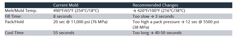
Table 1: Large Industrial Part, General Purpose ABS: Process Settings
Table 1: Large Industrial Part, General Purpose ABS: Process Settings
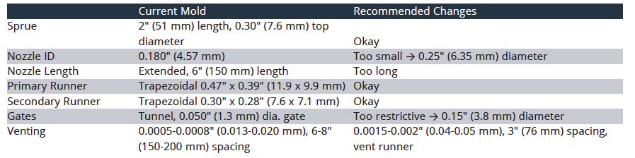
Table 2: Large Industrial Part: Runner and Venting Layout current
Table 2: Large Industrial Part: Runner and Venting Layout current
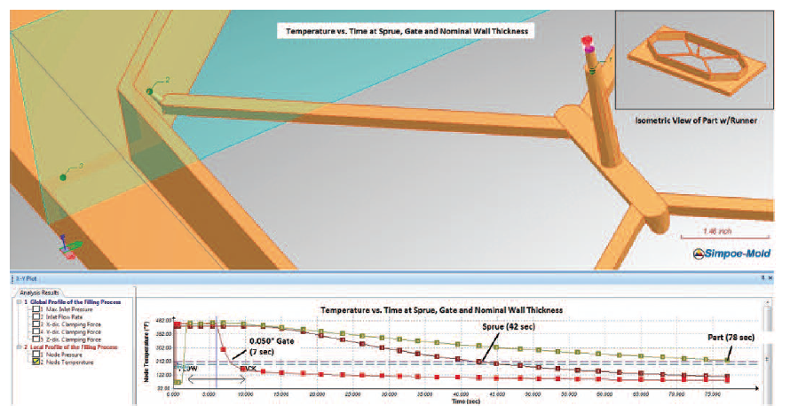
Figure 1: Temperature vs. time at sprue, gate, and nominal wall (Simpoe-Mold software).
Figure 1: Temperature vs. time at sprue, gate, and nominal wall (Simpoe-Mold software).
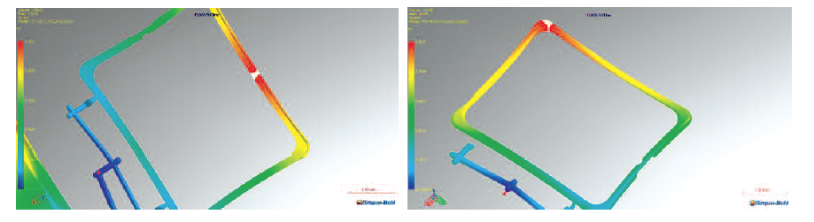
Figure 2: Left image: original two cashew gates with butt weld at end of fill; right image: one gate with part thickened 0.010" (0.25 mm); weld moved to corner
Figure 2: Left image: original two cashew gates with butt weld at end of fill; right image: one gate with part thickened 0.010" (0.25 mm); weld moved to corner
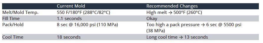
Table 3: Electronic Bezel + Base Family Mold: Process Settings
Table 3: Electronic Bezel + Base Family Mold: Process Settings
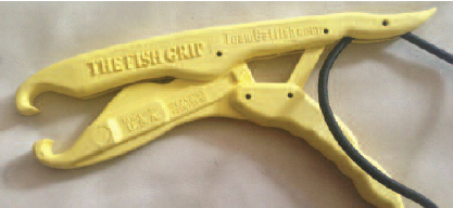
Figure 3: “The Fish Grip” molded with Thrive™ 20% cellulosefilled PP
Figure 3: “The Fish Grip” molded with Thrive™ 20% cellulosefilled PP
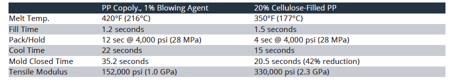
Table 4: Before and After Changes of PP Copolymer to Thrive 20% Cellulose PP
Table 4: Before and After Changes of PP Copolymer to Thrive 20% Cellulose PP
In last month’s edition of this series (July/August PE), a methodology for troubleshooting injection molding problems was discussed. In this article we show three troubleshooting examples of actual injection-molded parts. These examples show solutions to problems of parts having issues with long cycle times, weak weld lines, and insufficient part strength. (Note: For purposes of confidentiality, the descriptions of some of these parts have been changed.)
Example 1: Large Industrial Part with a Long Cycle Time and Warpage
The part and its problems
This part is a large industrial part, around two feet long with a nominal wall thickness of 0.25” (6.4 mm). The part was being molded with general purpose ABS. The mold was designed with a cold runner feeding four small tunnel gates. The mold was running with a long mold-closed time of 83 seconds, and required post-molding fixtures with large weights placed on the middle of the part to keep it flat.
Clues for causes
For this example it was assumed that the part’s design and cooling layout cannot be changed. We will look at simple changes to the runner system, tool venting, and processing conditions to reduce warpage and cycle time for this part.
Material: ABS is a forgiving material with reasonably easily flow and typically low warpage. At high shear rates some blooming can occur at the gates. Typically moderate fill times are used for ABS, and somewhat longer pack times are required.
Process setup sheet (Table 1): The fill time was set slow, at 8 seconds. This indicated possible issues with cosmetics and/or burning at vents. The pack pressure was set too high, at 11,000 psi (76 MPa), and set at a long time of 20 seconds. This indicated possible warpage issues.
Examination of mold and runner: Taking a look at the mold, we found the sprue and runner are adequately sized for this part, with a 0.47” (11.9 mm) trapezoidal primary runner and 0.30” (7.6 mm) secondary. However, the nozzle and gates were undersized. The current mold had 0.050” (1.27 mm) diameter submarine gates and a 0.180” (4.57 mm) diameter nozzle on the press with a 0.300” (7.62 mm) diameter at the top of the cold sprue (see Table 2). To make matters worse, the nozzle also had an extended tip which resulted in higher pressure losses. Finally, the venting was undersized for this mold, with 0.0005” (0.013 mm) deep vents spaced about every 6” to 9” (15 to 23 cm) on the parting lines. There was no venting at the runner system.
The above situation results in the need for higher melt temperatures, slower fill times (to avoid blooming at gate due to shear heating and burning at end of fill due to poor venting), higher pack pressures due to rapid gate freeze, and longer cool times to try to fixture the part in the mold. This all was evident in the process sheet.
Recommended changes
For ABS, the suggested gate thickness should be 50-70% of the wall thickness. For this part, with a 0.24” (6.1 mm) wall thickness, this works out to around 0.15” (3.8 mm) diameter. In Figure 1, a filling analysis of the current runner shows that the 0.050” (1.3 mm) gates freeze at around 6 seconds while the part requires more than 70 seconds to solidify. This clearly indicates the need for a larger gate. It should be noted that the part should be able to be ejected before it is fully solidified (around 50 seconds should be possible with proper gating and reduced melt temperatures).
The nozzle ID should be around 90% the diameter of the top of the 0.30” (7.6 mm) diameter sprue. This requires increasing the 0.18” (4.6 mm) nozzle ID to 0.25” (6.4 mm) diameter.
The vents in the mold were only around 0.0005” (0.0127 mm) deep x 0.100” (2.54 mm) wide. The land of the 0.0005” depth was too long at 0.250” (6.35 mm). The mold had no venting of the runner. The vent depths should be increased to 0.0015 to 0.002” (0.038-0.051 mm) (deeper near end of fill), with a land of 0.100” (2.54 mm). The vent spacing should be no more than every three inches (76 mm) and the runner should also be vented. If this was a new mold, full perimeter venting would have been optimal.
With the use of mold filling analysis, it was determined that the fill time should be reduced to 3 seconds, pack pressure set at 5500 psi (38 MPa) for 12 seconds, and cooling time set at 50 seconds. The mold temperature should be increased from 60 to 100°F (16 to 38°C) (for better surface finish), and the melt temperature reduced from 490 to 420°F (254 to 216°C). With these minor changes it was possible to reduce the cycle time by 18 seconds and mold a flatter part.
Example 2: Electronics Hard Case with Weak Weld and Poor Surface Cosmetics
The part and its problems
For this example, we will look at a two-piece case for an electronic device. This part was molded in ABS/PC in a 1+1 family mold. This part had problems with breakage of the top bezel component during disassembly of the bezel from the base. This breakage point was at a weld site. The nominal wall thickness for this part was 0.080” (2.0 mm) with some sections as thick as 0.100” (2.5 mm).
Clues for causes
Material: When molding with amorphous materials such as ABS/PC it is important to avoid butt-type welds at the end of fill, since these welds can be weaker and may fail under stress. Being at the end of fill, this weld line will form at lower pressures and temperatures. In addition, these weld sites can result in cosmetic issues such as burning or visible weld lines on the part.
Process setup sheet: The melt temperature was set at the upper limit for PC/ABS at 550°F (288°C). The pack pressure was also set high at 16,000 psi (110 MPa). These high settings indicate potential problems with short shots or weak welds.
Examination of mold and runner: For this 1+1 family mold of the bottom shell and top bezel, the cold runner and sprue were properly sized with a full round 0.24” (6.1 mm) diameter primary runner and 0.180” (4.57 mm) diameter secondary runner. The top diameter of the sprue was 0.22” (5.6 mm). The parts had cashew-type gates located on the bottom edge of the parts with 0.050” (1.3 mm) diameter gate sizes. The issue was the bezel had two gates located on one of the outside walls. This results in two weld lines—one between the gates and another on the opposite wall.
Recommended changes
In some cases, weld line strength can be improved by altering the part thickness to broaden the flow front angle. Due to the narrow width of this part, there was not much that could be done to broaden the flow front angle. The final solution involved two changes: First, one of the two gates on the bezel was welded shut, and the second was increased to 0.060” (1.5 mm) diameter. The thickness of the bezel was increased from 0.080 to 0.090” (2.0 to 2.3 mm). These changes removed the weld between the gates and pushed the far weld to the corner of the part. This resulted in both a far stronger and less visible weld (see Figure 2).
With the above changes, the melt temperature could be reduced from 550 to 500°F (288 to 260°C). The pack time was reduced from 8 to 6 seconds, the pack pressure was reduced from 16,000 psi to 5500 psi (110 to 38 MPa), and the cooling time was reduced from 18 to 13 seconds. The total mold closed time was reduced from 27.1 to 20.1 seconds with the elimination of the fracturing at the welds and improved part cosmetics (Table 3).
Example 3: Long Cycle Time and Material Not Rigid Enough
Sometimes the most dramatic improvements in cycle time and part performance are found by simply switching materials.
The part and its problems
United Plastics Molders Inc. makes a proprietary plastic “Fish Grip” pliers (www.thefishgrip.net) molded in a PP copolymer (Figure 3). This part is molded using a cold-runner family mold. The problem was that the neck of the pliers was twisting free when it was used for a large fish. The other issue was the long cycle times due to the thicker walls of the part and the use of a small amount of blowing agent. The nominal wall thickness was 0.24” (6.1 mm) with sections as thick as 0.74” (18.8 mm).
Recommended change
Months ago (March 2014 PE) I wrote about a new material technology called Thrive™ from Weyerhaeuser. It’s a cellulose-reinforced PP, which molds at low cycle times. The molders decided to give it a try. One change was made to the neck of the part to add a reinforcing surface in a thin section. In addition, some radii were added to some sharp corners on the part.
With this material, the mold-closed time was reduced from 35.2 to 20.5 seconds (42% reduction), with an almost doubling of the part stiffness due to the higher modulus of the material. The finished parts also had a higher quality feel than the PP copolymer and had improved appearance, with no visible surface sink (see also Table 4).
In this case, the problems of too weak a part, a long cycle time, and surface sink were solved by switching to a new material technology and making a few simple steel-safe changes to the mold.
In summary, in this month’s troubleshooting article, we showed three examples of how problems with injection molded parts were solved by first carefully understanding the material, processing, tooling, and part design relationships to help understand the cause of the problem. In addition, ideas were tested with filling analysis to quickly identify the optimal paths to both improve part quality and reduce the cycle times.
About the author:
Mark Rosen is principal of Corex Design Group Inc. (www.corexdg.com; email: mrosen@corexdg.com; phone: 201-891-1650).