
Troubleshooting Gels in Polyolefin Films
There are many types of gel defects—and ways to eliminate them
Previous Article Next Article
By Mark A. Spalding
The Dow Chemical Co., Midland, Michigan, USA
Troubleshooting Gels in Polyolefin Films
There are many types of gel defects—and ways to eliminate them
Previous Article Next Article
By Mark A. Spalding
The Dow Chemical Co., Midland, Michigan, USA
Troubleshooting Gels in Polyolefin Films
There are many types of gel defects—and ways to eliminate them
Previous Article Next Article
By Mark A. Spalding
The Dow Chemical Co., Midland, Michigan, USA
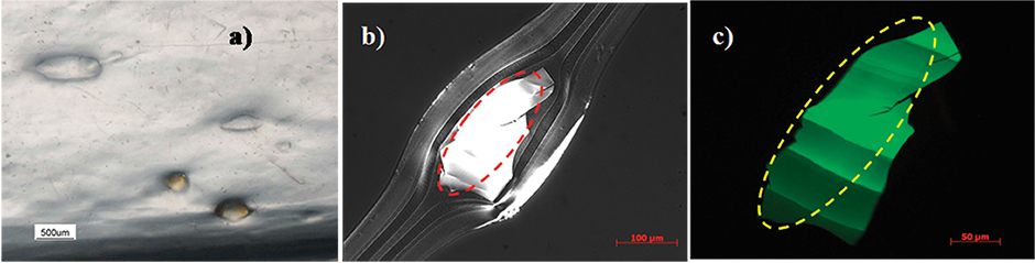
Figure 1: Photographs of gels: a) thermally crosslinked gel in LDPE film, b) highly oxidized gel photographed using transmitted polarized light, and c) the highly oxidized gel from b) fluorescing under UV light (images courtesy of E. Garcia-Meitin of The Dow Chemical Co.).
Figure 1: Photographs of gels: a) thermally crosslinked gel in LDPE film, b) highly oxidized gel photographed using transmitted polarized light, and c) the highly oxidized gel from b) fluorescing under UV light (images courtesy of E. Garcia-Meitin of The Dow Chemical Co.).
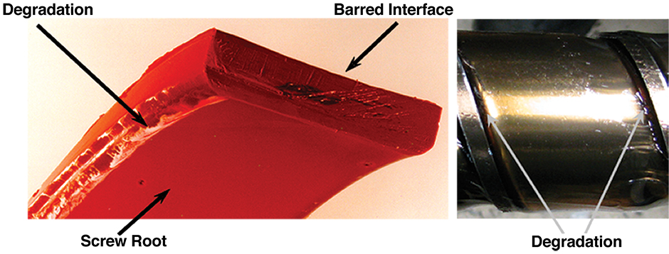
Figure 2: Photographs of resin degradation at the flight radii due to Moffat eddies.
Figure 2: Photographs of resin degradation at the flight radii due to Moffat eddies.
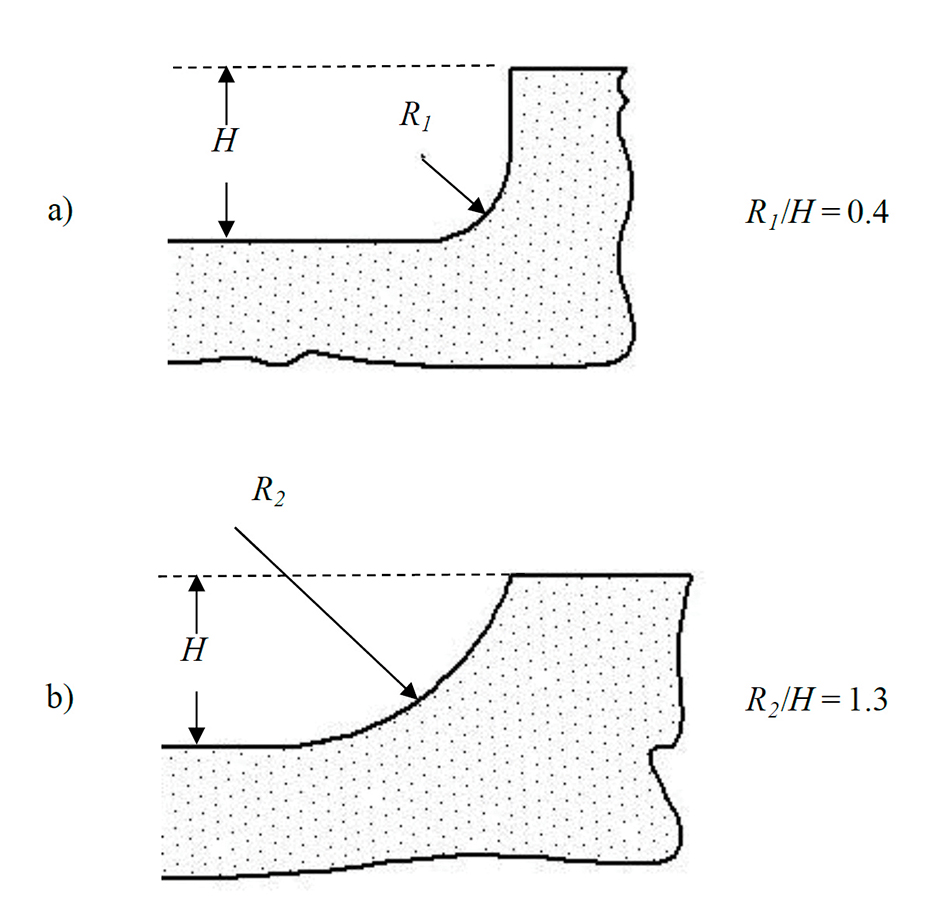
Figure 3: Schematic of flight radii: a) small flight radius (R1) that would likely cause a Moffat eddy, and b) a large flight radius (R2) relative to the channel depth (H); R2 would likely not form a Moffat eddy.
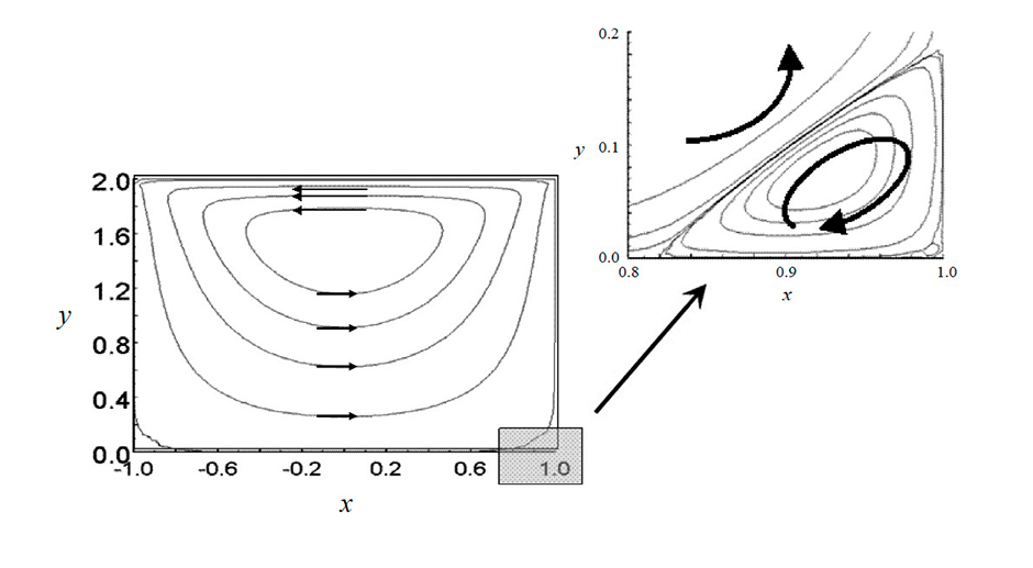
Figure 4: Two-dimensional flows in a screw channel. The arrows show the recirculation flows. The shaded area in the lower right corner is expanded to show the Moffat eddy.1
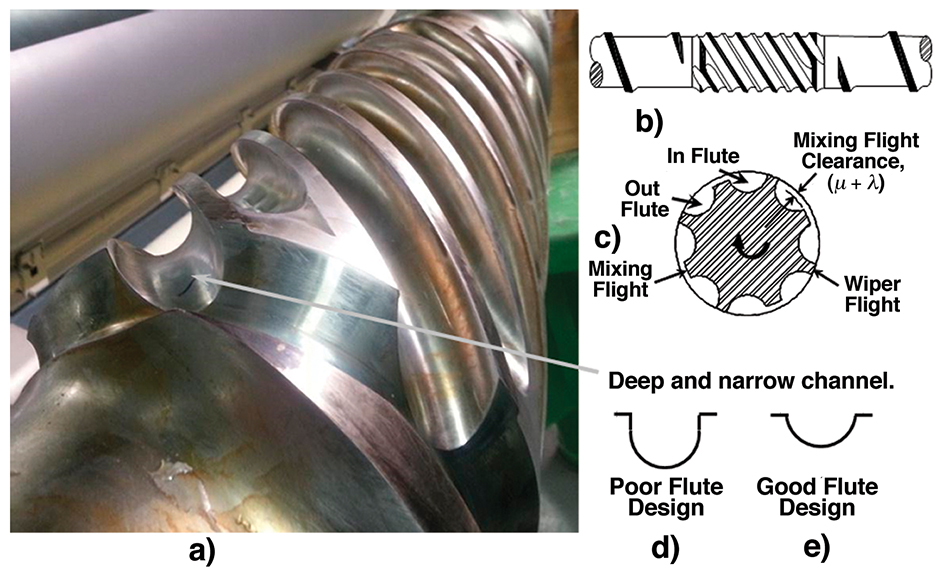
Figure 5: Maddock mixer: a) photograph of a poorly designed mixer with very deep flutes, b) schematic of a Maddock mixer, c) cross-sectional view of a mixer, d) flute shape for a poorly designed mixer, and e) a properly designed flute.
Figure 5: Maddock mixer: a) photograph of a poorly designed mixer with very deep flutes, b) schematic of a Maddock mixer, c) cross-sectional view of a mixer, d) flute shape for a poorly designed mixer, and e) a properly designed flute.
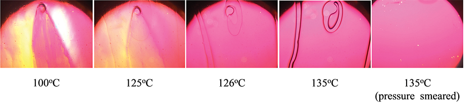
Figure 6: Photographs of an unmixed gel at select temperatures using a hot-stage microscope. The unmixed gel melted at about 135°C. When the gel was smeared by moving the glass cover slip, the stress was enough to disentangle the polymer chains such that the gel would not reappear upon cooling.
Figure 6: Photographs of an unmixed gel at select temperatures using a hot-stage microscope. The unmixed gel melted at about 135°C. When the gel was smeared by moving the glass cover slip, the stress was enough to disentangle the polymer chains such that the gel would not reappear upon cooling.
Gels can be a constant problem for the production of polyolefin film products. In the worst case, the gels can cause film breaks for cast film processes or can cause the bubble to break for a blown film process. These types of events increase the cost for production and often create high levels of scrap material that either has to be landfilled or recycled.
At the other end of the spectrum, gels can reduce the value of the product or keep the converter from selling film into a higher profit-margin market. In most cases, gels can be mitigated to very low levels by the optimization of the single-screw extrusion process.
Gel Types
The term gel is commonly used to refer to any small defect that distorts a film product. There are many different types of gels, including thermally crosslinked gels, highly oxidized gels, unmixed gels, and contamination. For gels originating from contamination, the converter must be able to identify the contaminant and then locate the source. Most resin manufacturers have the capability of identifying the contaminant.
Gels originating from contamination, however, are not the focus of this article. Thermally crosslinked gels and highly oxidized gels are typically generated in stagnant regions of a process. Here the resin is hot and has an extremely long residence time in the process, and it is often exposed to oxygen. Thermally crosslinked gels are produced in the absence of oxygen, while oxidized gels are produced in the presence of oxygen. (Photographs of these gel types are provided in Figure 1.)
Modern resin manufacturing processes, however, exclude oxygen from the system and are very streamlined, such that stagnant process areas with long residence times typically do not exist. As such, crosslinked and oxidative gels are likely not generated by the manufacturer.
Thermally crosslinked gels and highly oxidized gels are typically generated in stagnant regions of extruder screws and transfer lines. The most common regions for degradation are at the flight radii in the metering section and in deep flutes of Maddock-style mixers.1 Many other locations and design flaws, however, can create locations where resin can degrade. Improperly designed Maddock mixers and small flight radii are very common design flaws that occur in a large number of screws that are currently fabricated. Screws without these types of flaws can easily be designed with little to no additional cost if the designer is aware of the stagnation regions. Since the resin has extremely long residence time, antioxidant chemicals are not effective at mitigating these gels.
Flight Radii
The flight radii in the metering channel of the screw should be large relative to the local channel depth. If the radii are small, Moffat eddies can occur,2 creating regions with long residence times and thus locations where the resin can degrade. Resin degradation is shown in Figure 2 for polyethylene (PE) resins and screws with small flight radii in the metering section. For the screws in this figure, the ratio of the flight radii (R) to the local channel depth (H) was about 0.4 (R/H).
The flight radii size and local channel depth are shown in Figure 3. The R/H value can easily be estimated by visually observing the tangent point of the flight radius on the flight edge. An R/H of 0.4 is small for most PE applications. An R/H of about 1.3 is recommended.
Moffat eddies are secondary flows that cause eddies in regions with sharp corners. Eddies of this type are shown by the streamlines of Figure 4 (here the main flow is out of the plane of the page and towards the reader). The streamlines show the recirculation patterns due to the motion of the screw relative to the barrel wall. At the flight radii, the recirculation direction reverses and creates the eddy. The resin in the eddy has a very long residence time and thus is a place where degradation will occur. A simple process upset will knock the degradation off the flight and into the main flow, eventually creating defects in the film product.
Screws with small flight radii that create Moffat eddies not only allow resins to degrade, they also require longer times to purge between color changes or resin changes. The longer purge times are created by the long residence time of the older resin in the eddies. Screws that do not form Moffat eddies will purge in a significantly shorter time period.
Occasionally when a screw is rebuilt, a screw with large flight radii can be improperly rebuilt with flight radii that are reduced in size.3 Thus a screw that operates well can be altered during the rebuild process such that resin degradation will occur when the rebuilt screw is placed back into operation. It is recommended that the screw owner request that the rebuilder maintain the flight radii size as part of the agreement, especially for a first-time rebuild with a new fabricator. When the screw is returned to the plant after rebuilding, the screw should be inspected for flaws, including flight radii size, before the screw is placed into storage.
Maddock Mixers
Maddock-style mixers are commonly used on screws for polyolefin applications. The mixer is typically positioned in the metering section of the screw and downstream from a barrier melting section. They are used to trap and disperse solid polymer fragments that may be exiting the solids channel of the barrier section.
A schematic of a Maddock mixer is shown in Figure 5b). The mixer works by dividing the incoming flow into several in-flow flutes. Molten resin flows down the in-flow flute until it passes between the mixing flight and the barrel wall. Here is where the solid fragments are trapped and dispersed. The resin is then collected in the out-flow flute and conveyed to the downstream metering section. The number of flute pairs depends on the diameter of the screw.
The design of the flutes and the undercut between the mixing flight and the main flight are key design parameters for mitigating gels in polyolefin applications. For example, some designers cut the flutes very deep, as shown in Figure 5. This practice is done to minimize the pressure consumption and temperature increase for flow through the device. Deep flutes, however, can contribute to resin degradation, gels in the film, and long purge times during material changes. As a general guideline, the flute depth should not be deeper than half of the flute width.
The best method to determine if the screw design is creating resin degradation products is to remove the screw while it is hot. For this procedure, pellet flow to the hopper is stopped while screw rotation is continued. The screw is rotated until the resin-flow out of the die stops. Next, screw rotation is stopped and the transfer line is removed from the discharge end of the extruder. The hot screw should be pushed out about three diameters and then photographed and studied for indications of degradation.
Once the segment is studied, the hot resin should be removed from the screw using brass tools. Another three diameters are then pushed out and the process is repeated. The metal surfaces should appear clean with only mild discoloration. If a stagnant region exits, then dark-colored degraded material will occupy the space.
Unmixed gels (or entangled gels) are a common problem for PE resins. Unmixed gels are typically high molecular-weight polymer chains that are entangled and thus difficult to disperse during the extrusion process. These gels exit the die as molten material and then solidify first during the cooling process, creating the appearance of a gel as a solid polymer fragment.
They are analyzed using a hot stage microscope, where the gel is positioned between a specimen slide and a glass cover slip. The gel will melt as the stage temperature is increased. When the stage temperature is then decreased, the gel will recrystallize. Upon reheating, the gels will re-melt, and when the cover slip is pressed and moved using a dental tool, the gel will not reappear when cooled, as shown in Figure 6. The stress applied by the dental tool has disentangled the chains.
The unmixed gels can be removed in the extruder by increasing the stress level in the Maddock mixer. The stress level can be increased by decreasing the clearance on the mixing flight. The stress level required to disperse unmixed gels depends on the resin and the level of chain entanglement. In past experience, the stress level required to disperse PE unmixed gels is about 100 to 200 kPa.
A common design practice is to set the undercut clearance on the mixing flight to 1% of the barrel diameter. Thus for a 4.5-inch (114-mm) diameter extruder, the undercut clearance would be about 0.045 inch (1.1 mm). This undercut clearance may not be small enough to disperse unmixed gels. A clearance of about 0.025 inch (0.635 mm) will likely eliminate most unmixed gels without causing the extrudate temperature to increase substantially.
Summary
Converters do not have to accept crosslinked and unmixed gels in their film products. When gels persist over time, it is highly likely that the screw is not designed properly and that it contains regions where the resin is stagnant. These stagnant regions can easily be eliminated from a new screw by following the simple guidelines presented here.
References
- Campbell, G.A. and Spalding, M.A., Analysis and Troubleshooting of Single-Screw Extruders, Hanser Publications, Munich (2013).
- Moffat, H.K., “Viscous and Resistive Eddies Near a Sharp Corner,” J. Fluid Mech. 18, 1 (1964).
- Spalding, M.A., Womer, T.W., and Campbell, G.A., “Rebuilding Screws for Injection Molding Processes,” SPE ANTEC Technical Papers 61, 1809 (2015).
 About the author… Mark A. Spalding is a Fellow with The Dow Chemical Company in Midland, Michigan. He has performed research in all aspects of single-screw extrusion and has applied this fundamental knowledge to troubleshooting extrusion processes. He also coauthored the 2013 book Analyzing and Troubleshooting Single-Screw Extruders with Gregory A. Campbell of Castle Associates. Contact Mark Spalding at U.S. 989-636-9849 or maspalding@dow.com.
Note: The author and Gregory Campbell will be presenting a single-screw extrusion troubleshooting seminar at Polymers Center of Excellence in Charlotte, North Carolina, USA, on November 3-4, 2015. For more information or to register, go to www.4spe.org/singlescrew.