Cold Runner Design: It’s All About the Details
Common features designed into a mold can create flow variations
Previous Article Next Article
By David A. Hoffman
Beaumont Technologies, Inc., Erie, Pennsylvania, USA
Cold Runner Design: It’s All About the Details
Common features designed into a mold can create flow variations
Previous Article Next Article
By David A. Hoffman
Beaumont Technologies, Inc., Erie, Pennsylvania, USA
Cold Runner Design: It’s All About the Details
Common features designed into a mold can create flow variations
Previous Article Next Article
By David A. Hoffman
Beaumont Technologies, Inc., Erie, Pennsylvania, USA
"The term “steel variation” is a catch-all phrase used to describe any source of variation not related to viscosity variations."

Figure 1: Puller pins (arrows) used in a two-plate mold design (left) and a three-plate mold design (right).

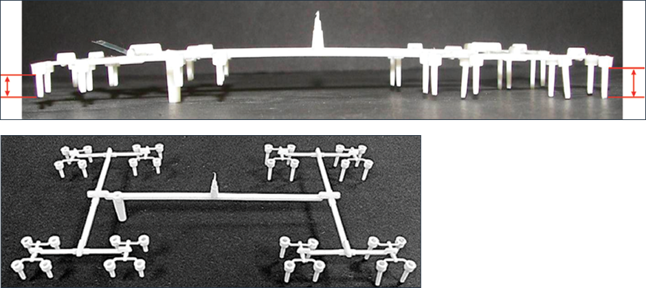
Figure 2: A short shot of a cold runner from a small, 32-cavity, three-plate mold. As indicated by the red lines/arrows, one half of the mold is filling before the other half (and the root cause is not gravity in this case).
In the March 2015 Plastics Engineering’s “Consultant’s Corner” article, we talked about the benefits of using flow group IDs versus traditional cavity ID numbering methods. Flow group IDs relate directly to the pressure drop equation (Equation 1 below) and are designed to help identify the root cause of mold filling and part quality variations.
Equation 1

Using flow groups helps separate out variation root causes into either steel or viscosity variations.
The term “steel variation” is a catch-all phrase used to describe any source of variation not related to viscosity variations. In general these variations are found within the l and r variables in the equation. Equation 1 is based on a round channel, such as a full round runner system, nozzle, or sprue. If the plastic is flowing through a rectangular channel, then the equation changes slightly; of most interest for this article, we are talking about the r variable becoming w (width) and t3 (thickness cubed). Below are a few common sources of these types of variations:
- gate land and diameter,
- machining of the runner,
- wall thickness (core/cavity dimensions),
- venting,
- cold slugs, and
- hot runner temperature distribution and manufacturing.
As you can see, there are numerous sources of steel variations. Some of them are directly related to the steel, while others are more general in nature. The focus of this article will be on common design features in both two-plate and three-plate molds that are actually designed to create variations in the process and product quality. You may be asking yourself “Who would ever design a feature into the mold that is designed to create variations?” And that is certainly a reasonable question. And the answer is simply, “those who didn’t know it would have any impact on the process and product quality.”
Designed-in Variations
The sources we are talking about are features such as puller pins (sucker pins), sprue picker stems, and vacuum pads. These features are designed into the mold with the purpose of aiding in the removal of the cold runner system from the mold, and/or the gate from the part. The Figure 1 images illustrate puller pins used in two-plate and three-plate mold designs.
The placement and overall design of these features are not usually well thought-out in many mold designs. We have seen molds with puller pins of different sizes being used. If the puller pins are in the main flow path of the material, as shown in Figure 1, the plastic must flow around them. Considering the pressure drop equation, this ultimately affects the r variable. Since r is raised to the fourth power, we can understand that small changes in radius will have a large impact on pressure drop. Therefore, care must be taken when designing and placing such features in the mold, as it has been shown numerous times over that these features can absolutely impact the mold performance, flow balance, process window, and overall part quality (as in Figure 2, for example).
Recommendations & Conclusions
Our recommendations when designing these features into your molds are as follows:
- Design puller pins such that they do not restrict the main flow path.
- Where appropriate, add the particular feature to both sides of the sprue and at each side of the preceding intersection.
As people begin to understand more about plastic flow and the variables in the pressure drop equation, they begin to understand how small differences can have a big impact on the molding process and part quality. Many times those small differences are found in the melt delivery system, whether it be a hot runner or cold runner or a combination of the two.
Unfortunately the general perception in the industry is that “the runner doesn’t matter much to part quality, so who cares?” But as with anything, the devil is in the details, and those details are all too often overlooked and misunderstood. A runner design that has been engineered for plastic flow needs to consider these details, along with a lengthy list of other considerations that we will continue to dig through.
After all, the plastic that makes up the parts has to travel through the runner system. And what the plastic experiences along that trip will influence the final destination—which is your molded part.
About the author… David Hoffman has worked as a part and mold designer, process engineer, and engineering manager. He’s currently the senior instructor/education development manager for Beaumont Technologies, Inc.’s Plastics Education Courses. Contact him at U.S. 814-899-6390 ext. 131 or dhoffman@beaumontinc.com.
