Joining underhood automotive parts:
A primer for choosing the right process
Previous Article Next Article
By Craig Birrittella, Automotive Segment Manager, Business Development,
Branson Ultrasonics, a business of Emerson
Joining underhood automotive parts:
A primer for choosing the right process
Previous Article Next Article
By Craig Birrittella, Automotive Segment Manager, Business Development,
Branson Ultrasonics, a business of Emerson
Joining underhood automotive parts:
A primer for choosing the right process
Previous Article Next Article
By Craig Birrittella, Automotive Segment Manager, Business Development,
Branson Ultrasonics, a business of Emerson
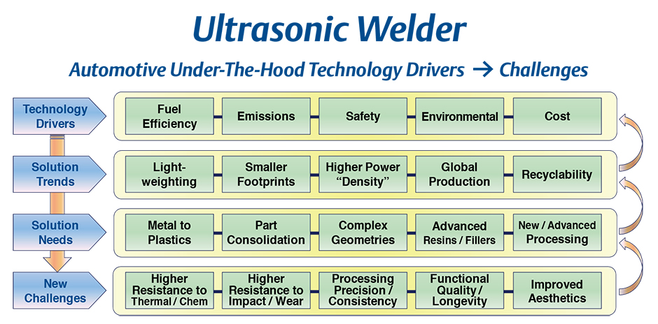
Table 1: Technology drivers, new challenges. All images and tables courtesy of Branson Ultrasonics
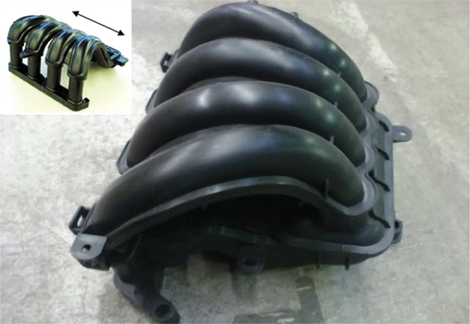
Figure 2: Vibration welded air intake manifold. Inset, Direction of linear motion of top part relative to bottom part.
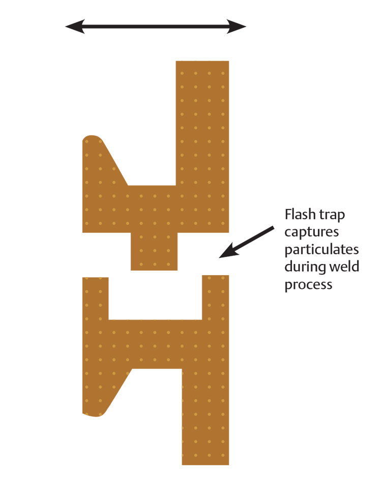
Figure 3: Typical vibration weld joint.
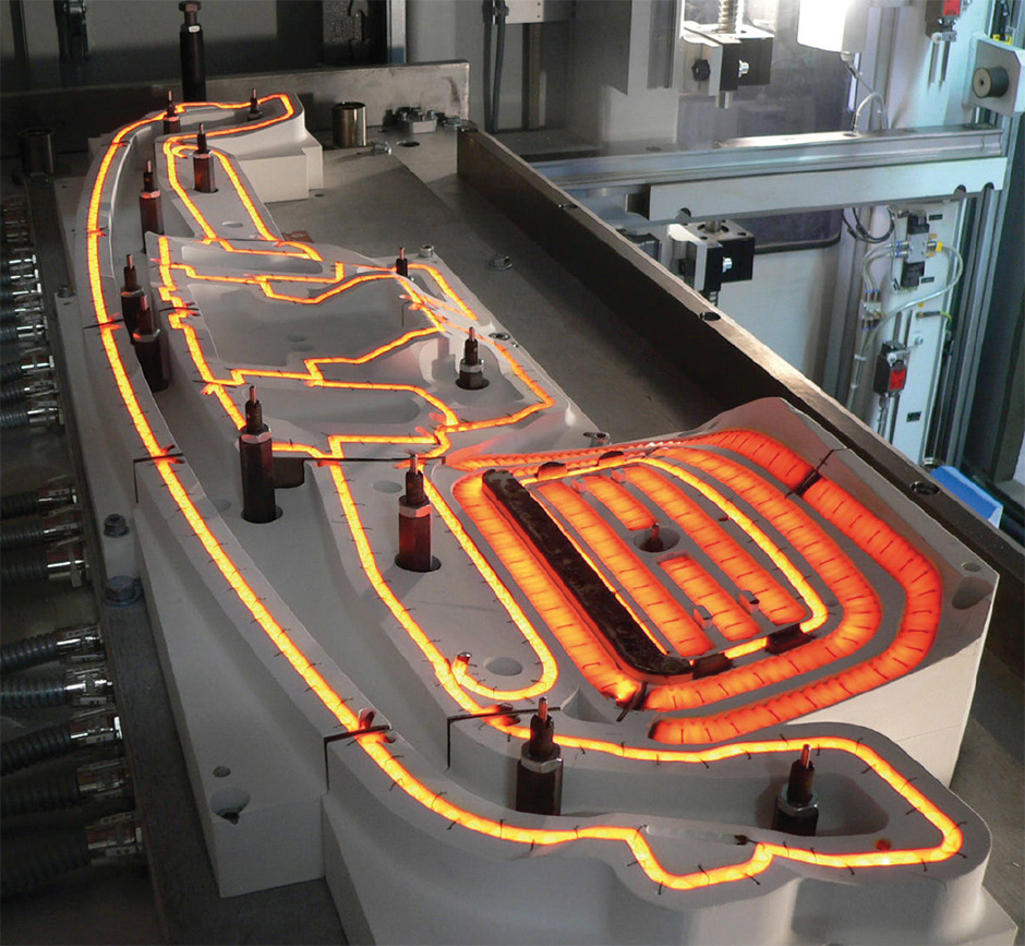
Figure 4: IR metal foil emitter assembly. Follows the shape and contours of the weld interface.
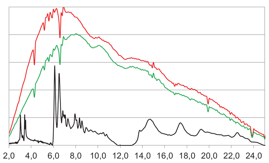
Figure 5: Metal foil energy emission (red/green) and PA6 GF30 absorption efficiencies (black) over a range of wavelengths.
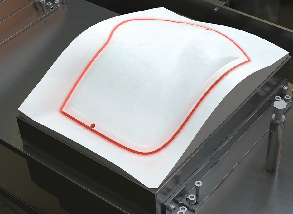
Figure 6: IR emitter for CVT application. Contoured metal foil matches part shape.
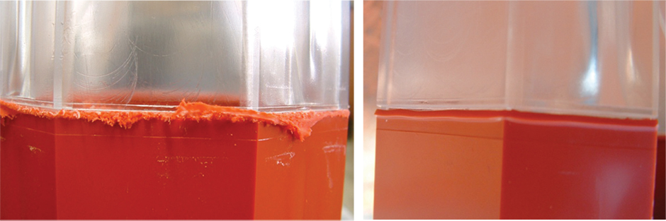
Figure 7: Left, Typical vibration weld flash from PC/ABS test specimen. Right, CVT weld flash from same PC/ABS test specimen.
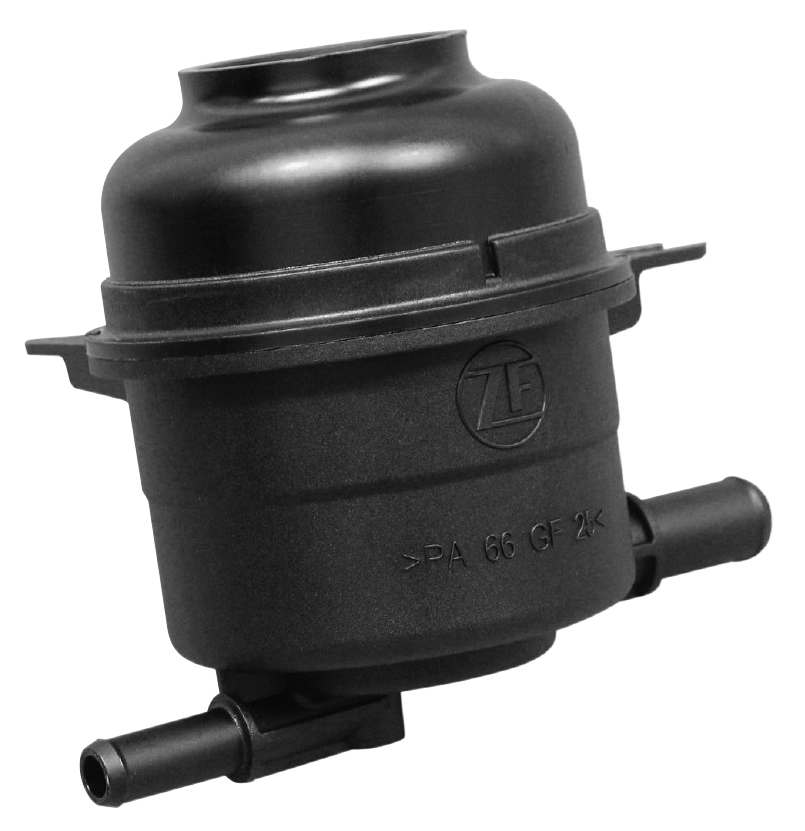
Figure 8: Fluid Reservoir. PA6 GF25. Clean weld, hermetic seal required.
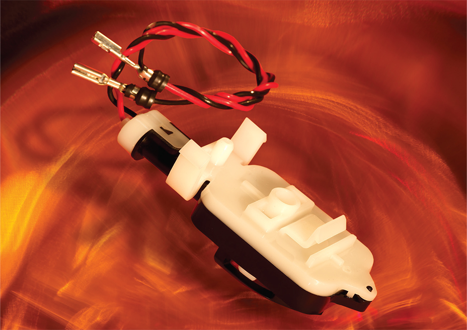
Figure 9: Control module PBT.
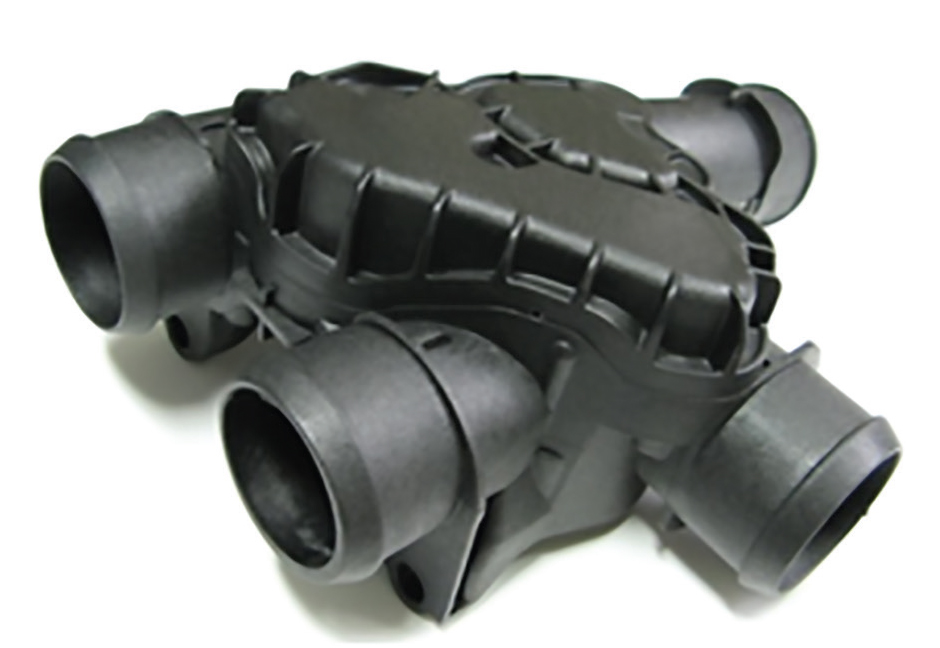
Figure 10: Coolant manifold
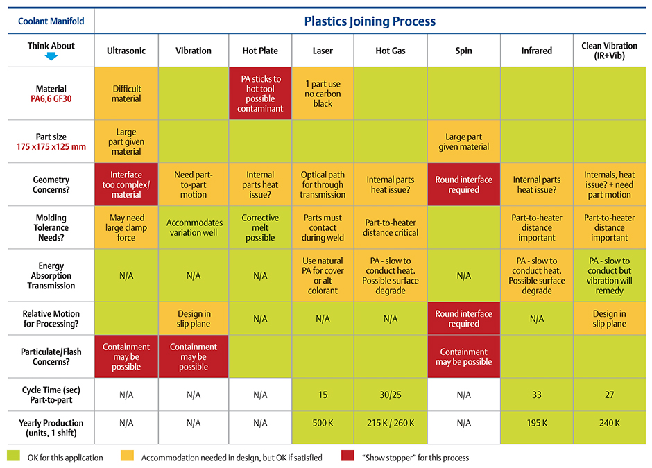
Table 2.
Keys to good decision making
- Maintain a solid understanding of the latest advancements in plastics joining technologies and polymer science.
- Maintain a “process neutral” approach and consider a variety of joining technologies during the design phase. Be open to using whatever is shown to be the most effective solution for your application.
- Evaluate the key variables that will determine your best solution, including material to be used, size and complexity of part design, production volume/cycle time, weld cleanliness and aesthetics, and expertise and support of equipment suppliers.
- Involve all stakeholders early in the design process, including resin suppliers and processing equipment suppliers.
It has been more than 25 years since polyamide (nylon) was first used in place of cast aluminum to mass produce an air intake manifold in the United States. Since then, replacing metal components with plastics in automotive under-the-hood applications has become a continuing trend.
In recent years, key technology drivers, led by fuel efficiency and emissions reduction, have presented tougher challenges, demanding innovative design solutions that rely on advances in engineered polymers and processing (see Table 1).
Success so far has been a result of the industry redesigning parts and assemblies for plastics, and not simply replacing metal components one by one. Design teams have had to engage resin suppliers and processing equipment suppliers at early stages of development to optimize all aspects of part design, resin material and processing.
We have seen, for example, high-performance polymers such as PPS and PPA replace metal in assemblies that are closer than ever to the engine combustion area. Here again, success has been the result of a team approach simultaneously evaluating materials with higher thermal resistance, the processing requirements of such materials, and part design.
Given such complex challenges, when considering plastics joining solutions, it is important to understand the advantages and limitations of a wide range of joining technologies. Of equal importance, a “process neutral” approach should be adopted at the outset of the design phase and maintained while evaluating the many available technologies. Plastics joining solutions providers should be engaged early to help determine the best fit for the application. This will dramatically improve the design, manufacturability and functional performance of the application, and will reduce the risk of costly redesigns, rework of prototypes, and scheduling delays caused by a lack of information about plastics joining technologies.
Following is an overview of certain plastics joining technologies deployed in under-the-hood applications that involve engineered and high-performance polymers. We then present a sample application to illustrate the thought process used to determine the most appropriate solution.
Vibration welding uses heat energy generated when one part is held stationary while the other part is moved in a linear, back-and-forth motion. The heat generated initiates a controllable meltdown at the interface of the parts. Vibration welding requires that the part interface accommodate the relative motion inherent in the process. Typical motion is 1 mm in each direction for 240 Hz welding and 2 mm in each direction for 100 Hz welding.
Figure 2 shows an air intake manifold made from PA6 GF30. While the geometry is complex, the parts are designed so that there is a part-to-part orientation that will accommodate the linear motion required by the process. Jagged weld flash and particulates are typical by-products of vibration welding. “Flash traps” are designed into the parts (Fig. 3) to contain the flash produced during the weld. However, in some designs, part geometry does not always allow for this method of flash containment.
Infrared welding uses energy that is radiated by gray body emitters mounted on a movable platen. It is a non-contact process in which the parts to be joined are brought close to the emitter platen (approximately 1 mm) as energy is absorbed at the weld interface. The parts are then pressed together, achieving a bond that is controlled during meltdown.
Infrared emitters are typically either glass bulb or metal foil (Fig. 4). To optimize energy absorption in the weld area, the emitters should have an output energy profile that accommodates the absorption efficiency profiles of the many plastics used (Fig. 5). Medium wave emitters have this characteristic and are best for plastics joining.
Clean vibration technology (CVT) combines IR preheating (Fig. 6) followed by a vibration weld cycle. The preheat step enables the combined process to bypass the dry friction phase in traditional vibration welding, which generates the common particulate and jagged flash (Fig. 7). In CVT welding, the flash produced is clean and compact, similar to that of IR welding. Figure 8 shows a fluid reservoir requiring a hermetic seal, high strength and a clean weld joint. Geometry constraints did not allow for the option of flash traps so weld aesthetics were also important.
Laser welding uses energy typically generated by one or more 980 nm laser sources to heat the parts during the weld cycle. Several techniques exist that deliver the laser energy from its source to the plastic parts, including simultaneous, quasi-simultaneous, and trace welding. All techniques deploy the concept of through transmission welding, in which the parts are clamped together as the laser energy is transmitted through one part and absorbed by the second part at the mating interface. The absorbed heat is conducted across the part interface, thus achieving a controlled melt in both parts.
Laser welding accommodates highly complex parts, achieves high-strength welds, and in the case of simultaneous laser welding, has very fast cycle times. The resulting weld joint has very little flash and virtually zero particulate. No relative motion or high-temperature heat sources are required during the weld process, so parts with delicate internals are often candidates for this technology. Laser welding requires parts with good dimensional tolerances and also requires one part to have a higher transmission/absorption ratio (at 980 nm) relative to the other. This is usually accomplished by using selective colorants in the parts.
Figure 9 shows a laser welded electronic control module that has delicate internals and a very thin wall, creating very little room for a weld joint.
Hot gas (convection) welding uses the energy in electrically heated air that is directed out of an array of nozzles mounted on a movable platen. It is a non-contact process in which the parts to be joined are brought close to the air nozzle platen (
Other technologies are, of course, available for plastics joining that remain viable for a number of under-the-hood applications. These include hot plate welding, spin welding and ultrasonic welding. While these processes are not described in-depth here, they are also an important part of an overall technology evaluation for any application.
To illustrate the process of determining the most appropriate plastics joining solution for a particular application, consider the coolant manifold shown in Figure 10. Assume for a moment that the part shape has yet to be finalized and that the following information is known:
- Required material: PA66 GF30
- Part size: 175 mm x 175 mm x 125 mm
- Production volume: approximately 175,000/year
Special requirements include: Strict avoidance of particulate break-off inside the part that would contaminate fluid. Hermetic seal. Burst pressure of 14 bar (200 psig) minimum.
Table 2 demonstrates a decision matrix of relevant points to consider in the left column with color codes in each column indicating whether the corresponding joining technology is viable. In addition to color coding, select comments are included in certain areas for clarification.
The analysis shows four viable processes, given the design requirements as long as the comments in yellow boxes are satisfied. Material testing should be done with any process considered to further vet out any challenges. A plastics joining equipment supplier should have lab equipment to test each process and be willing to weld test samples and assist with weld strength testing to help in the optimization process.
If multiple processes are able to meet the requirements, as in the example above, one must also consider production criteria. The four viable processes all meet the yearly capacity requirement, so a number of production considerations like these can help focus the selection:
- What is the capital budget for the program versus the cost of equipment needed?
- Is the takt time of the process consistent with the production plan?
- If one process is much faster than needed, is there another application that can be run in the same machine?
- If more capacity is desired (say for safety stock production), is a multicavity tool an option?
For optimum results, it is important to not make a technology decision based on whether your company has experience with an appropriate technology. Being open to new technologies and methods helps ensure the most effective solution gets chosen.
In summary, four overarching considerations can guide you to determining the best plastics joining technology for your application, and thus help you achieve success in solving the tough challenges the automotive industry faces.
ABOUT THE AUTHOR
 Craig Birrittella is the Automotive Segment Manager, Business Development for Branson Ultrasonics, a business of Emerson.
During Birrittella’s 20-year career at Branson, he has received a US Patent for a lens that adapts laser energy for uniform welding, and has focused on a variety of technical areas, from vibration, clean vibration, infrared, and laser welding to application development, and custom machine and tooling design.
Birrittella has served Branson in a variety of capacities, including mechanical engineer, engineering manager, director of plant operations, product manager and director of global product management, before assuming his current position.