Foamcore Blow-Molded Structural Components for Transportation Applications
Previous Article Next Article
By Steven R. Sopher
JSP, Pittsburgh, Pennsylvania, USA
Foamcore Blow-Molded Structural Components for Transportation Applications
Previous Article Next Article
By Steven R. Sopher
JSP, Pittsburgh, Pennsylvania, USA
Foamcore Blow-Molded Structural Components for Transportation Applications
Previous Article Next Article
By Steven R. Sopher
JSP, Pittsburgh, Pennsylvania, USA
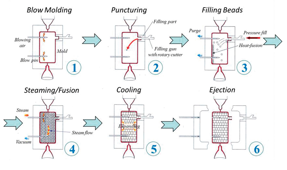
Figure 1: Foamcore process overview.
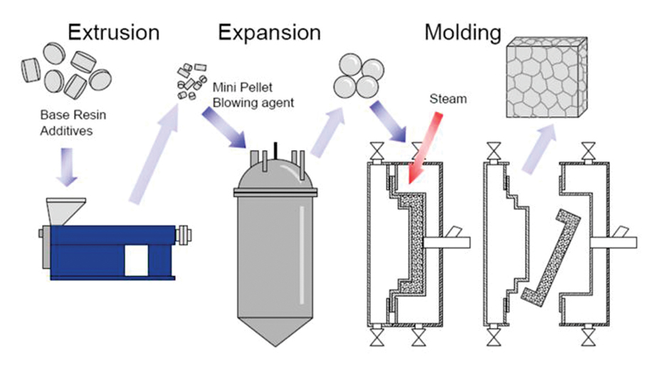
Figure 2: Production stages of expanded polyolefin particle foams.
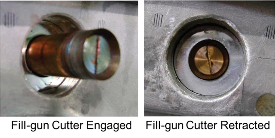
Figure 3: Foamcore tool details with fill-gun.
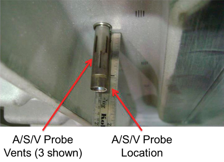
Figure 4: Foamcore tool details with A/S/V probe engaged.
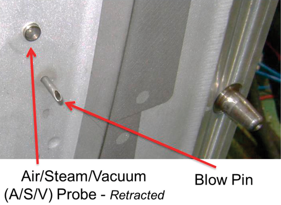
Figure 5: Foamcore tool details with A/S/V probe retracted back into the tool.
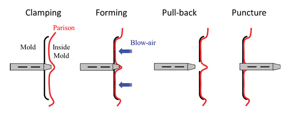
Figure 6: Foamcore A/S/V pin action.

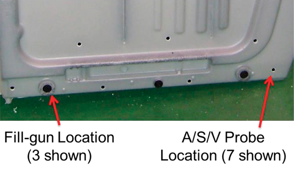
Figure 7: Foamcore part details with A/S/V probe and fill-gun locations.
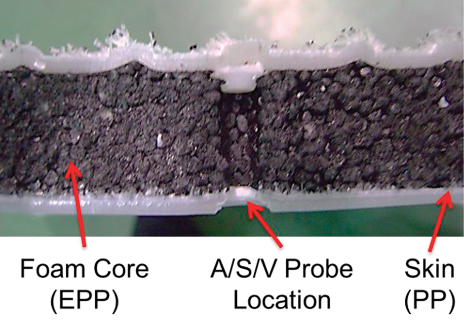
Figure 8: Foamcore cross-section with A/S/V probe location.
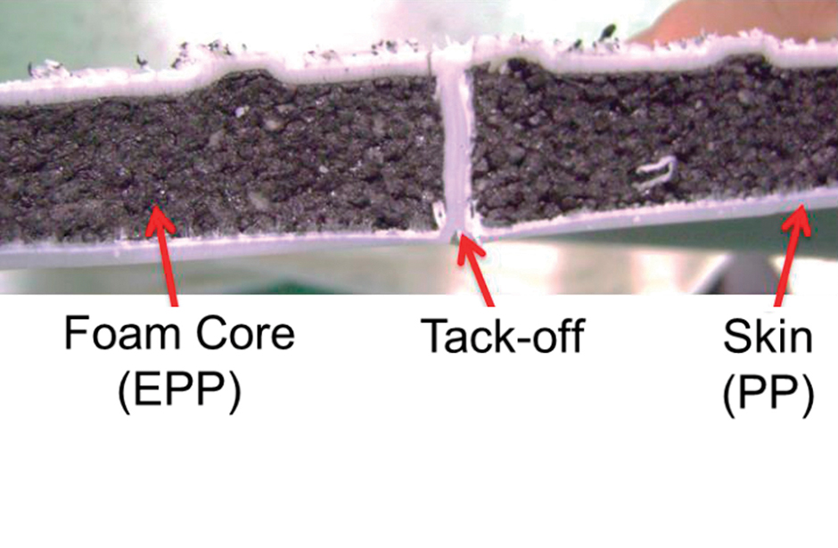
Figure 9: Foamcore cross-section with tack-off.
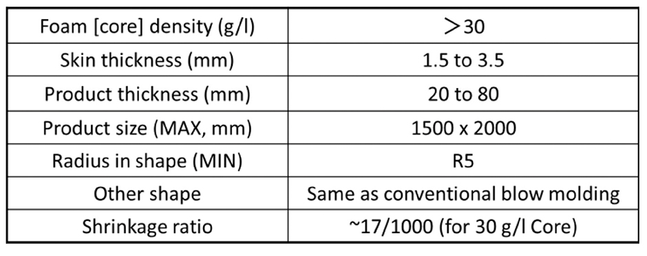
Figure 10: Foamcore part design guidelines.
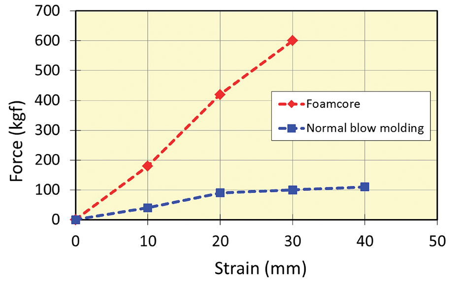
Figure 11: Flexural strength property comparison.
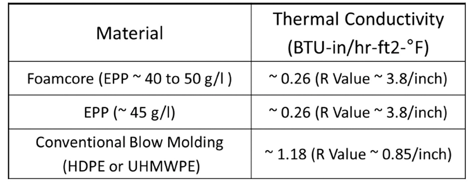
Figure 12: Foamcore thermal insulation performance.

Figure 13: Rear seat back, front view.
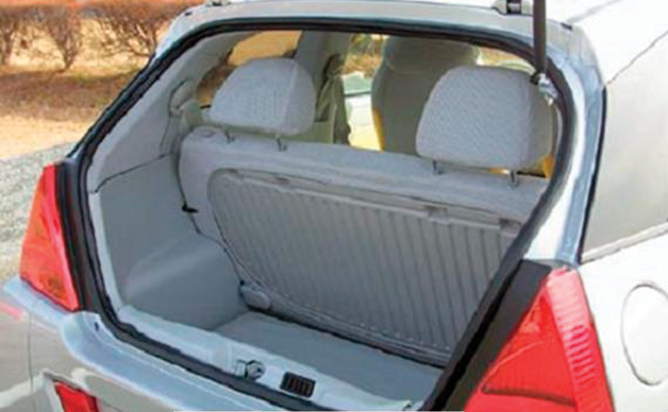
Figure 14: Rear seat back, in vehicle.
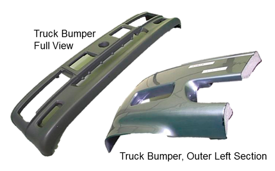
Figure 15: Truck bumper.
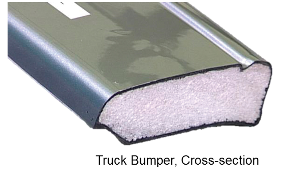
Figure 16: Truck bumper cross-section.

Note: This paper was singled out as “Best Paper” by the awards committee of the SPE Blow Molding Division earlier this year at ANTEC® Orlando. To access other ANTEC papers, contact SPE customer service at U.S. 203-775-0471.
With emphasis on weight reduction throughout the transportation industry, there is a renewed effort to remove as much mass as possible to improve vehicle performance. JSP has developed and optimized a blow-molding process that combines traditional blow molding with an injection-molded particle foam core. This process, called Foamcore, utilizes traditional blow-molding equipment combined with a particle foam injection unit to produce a composite blow-molded part with a solid foam core.
JSP’s Foamcore technology allows for simpler designs, higher strength-to-weight ratios, and lower part weights, all while using existing tooling (with minor modifications). Multiple polymers can also be used, including polypropylene (PP), polyethylene (PE), polystyrene (PS), and others, for both skin and core materials.
This paper will describe recent advancements of this technology, and how they allow for improved mechanical properties to be realized in the area of transportation applications for structural and semi-structural components. Other features discussed include improvements in thermal insulation and sound abatement, as well as recyclability and end-of-life requirements.
Introduction
JSP’s Foamcore technology is a hybrid combination of traditional blow molding and expanded bead-foam compression steam-chest molding. Using this method, a blow-molded part can be produced with a self-contained foam core consisting of PS-, PP- and/or PE-based particle foams. This technology allows the production of single-layer traditional blow-molded parts with a foamed inner core in a single shot.
Traditional extrusion blow molding begins with extruding the base resin to form a parison, which is drawn down between two mold cavities. The parison is then clamped between the closed mold cavities, and air is blown into it (via one or more blows) to form the cavity. The action of the air, with the help of external vacuum assist (on select portions of the tool), allows for the formation of the part. In some cases (for structural parts), moving slides are used to form internal ribs, or “tack-offs,” which give the part structural support. Once the plastic has cooled and hardened, the mold opens up and the part is ejected.
Blow molding can consist of a single layer or multiple layers of different resins or combinations of resin blends. In the case of structural blow molding, a single layer is generally used. In order to control the structural rigidity of the blow-molded part, the parison thickness can be controlled, resulting in a controlled part thickness for additional support. Resin fillers can also be used. Many structural blow-molded parts using PP or PE (including HDPE, HMWPE, and UHMWPE) also add chopped glass or other mineral fillers (talc, etc.) to achieve different levels of structural support.
Technology Overview
The Foamcore process uses traditional extrusion blow molding technology using the accumulator method to drawn down the parison. After the mold is closed and the parison is blown to form the cavity, the Foamcore technology is engaged. The basic steps are as follows: (1) blow molding, (2) puncturing cavity, (3) filling bead foam, (4) steaming, (5) cooling, and (6) ejection.
Figure 1 illustrates the basic steps of the Foamcore process. All of these steps take place as the tool is closed using a standard blow-molding tool and press configuration, along with standard blow-molding resins including PS, PP (neat, talc filled, glass filled, etc.) and PE (HDPE, UHMWPE, etc.). While these resins function as the outer layer of the traditional blow-molded part, the inner cavities are injected and filled with expanded polystyrene (EPS), expanded polypropylene (EPP), or expanded polyethylene (EPE). These EPS, EPP, or EPE materials serve as the foam core and provide structural support to the finished part.
JSP’s Foamcore technology is a unique hybrid combination of traditional blow molding and traditional particle-foam compression steam-chest molding. By combining these two technologies, the result is the ability to produce a much lighter structural product with better thermal insulation and sound insulation values. Applications include transportation (automotive, agricultural, aviation), construction, sporting goods, and any application where traditional blow-molding parts require additional structural support.
Additional benefits include simplicity of design (no complicated tack-offs required), cost reduction (from component consolidation), weight reduction (structural core allows for thinner skin), and of course, insulation and acoustical benefits. The level of structural support can be optimized by increasing or decreasing the density of the particle foam used inside the part. Molded foam densities from 30 kg/m3 to 225 kg/m3 are possible.
Particle Foam Background Details
Shape-moldable particle foams can be broken down into four primary categories: (1) polystyrene-based (EPS), (2) polypropylene (EPP), (3) polyethylene (EPE or xEPE), or (4) copolymer or interpolymer (PS/PE, PS/PP, PP/PPO, SAN). There are other newer types of particle foams, including those composed of TPU, PLA, PHA, PBS, and other resins and resin blends, most of which have a limited use due to cost and availability.
Most PS particle foams or styrene-based particle foam blends are produced using suspension polymerization, which produces expandable particle foam using a VOC such as pentane and/or butane. Expanded polystyrene particle foams can also be produced, whereby a resin particle is secondarily expanded using either an inert or VOC gas.
While many polyolefin particle foams can be produced using either inert gas or VOCs, all polyolefin particle foams produced by JSP are expanded using an inert gas batch expansion process. Figure 2 contains a basic diagram showing the production stages of expanded polyolefin particle foams.
Manufacturing Process Details
JSP’s Foamcore process uses standard blow-molding equipment and standard tooling, with one side modified to allow for filling and steaming of particle foams. The modification of the tooling includes the installation of one or more fill-gun locations and multiple probes used for air, steam, and vacuum (A/S/V probes). Both the fill-gun(s) and A/S/V probes are capable of engaging and retracting through the formed parison and into the blow-molded cavity. Standard blow-molded tools can be modified to allow for retrofitting these fill-guns and A/S/V probes.
In addition to the blow-molding tool modification, additional secondary equipment is required to properly fill and steam (fuse) the particle foam inside the blow-molded cavity. This secondary equipment consists of a pressurized particle-foam fill system (capable of 4 bar pressure), source of steam (capable of 4 bar pressure), source of air (6 bar pressure), and vacuum.
Foamcore technology combines the machine capabilities of standard blow-molding and steam-chest compression molding. JSP has developed a stand-alone Foamcore unit with a self-contained particle-foam fill system and A/S/V delivery system, with the addition of a separate control logic system capable of interacting with standard blow-molding machines. This system design can be made portable so that it can be readily integrated into multiple blow-molding machines are needed.
The fill-gun design used for the Foamcore technology is unique in that its special design combines cutting through the formed parison (via a rotating cutter head/blade), engaging the fill-gun tip, and filling the particle foam into the blow-molded cavity. Figure 3 shows the details of the fill gun as viewed from inside the mold cavity. The left picture shows the fill-gun tip engaged into the cavity, which is how the formed parison is initially punctured to allow for the particle foam to be injected into the cavity. The right picture shows the fill-gun retracted back into the fill-gun recess (stationary or “closed” position). During the filling of the particle foam, the fill-gun tip retracts back from the stationary position to allow for the particle foam to be injected into the cavity, and once the cavity is filled, the fill-gun tip then moves back to the stationary or “closed” position. It remains in this position during the remaining cycle steps.
The A/S/V probes are essentially hollow, movable, multi-function actuators that serve to deliver air and steam and draw vacuum (independently as required) during the Foamcore process. The control system employed by the Foamcore process (as described above) allows for independent control of each A/S/V probe location.
The purpose of the A/S/V probes is three-fold. First, they deliver air to the cavity to assist the blowing or forming of the parison, and maintain cavity pressure. Second, they deliver the steam necessary to fuse together the particle foam inside the cavity. Third, they draw vacuum to evacuate the cavity and remove the steam condensate during and after the steaming step. They are capable of maintaining the vacuum during the cooling step, which serves to remove excess heat from the inside part, thus minimizing the cooling time and possibly reducing cycle time.
Figure 4 shows the details of the A/S/V probe as viewed from inside the mold cavity. The picture shows the A/S/V probe engaged into the cavity, which is how the formed parison is punctured (using a sharpened tip) to allow for the probe to deliver air or steam or draw vacuum. The A/S/V probes are engaged during the time the fill-gun tip is engaged. Note the shape of the probe tip and the integrated vents around the circumference of the probe through which the air and steam flow, and through which the vacuum is drawn. Also note the size (length) of the A/S/V probe in the picture. These can be tailored to the specific thickness of the part based on the location of each A/S/V probe within the part.
Figure 5 shows the A/S/V probe retracted back into the tool (stationary or “closed” position). These A/S/V probes remain engaged during the filling, steaming, and cooling steps, and are retracted prior to mold open and part ejection. Figure 5 also shows the blow pin, which is adjacent to the A/S/V probe.
Each A/S/V probe is capable of steaming a volume of ~0.5 to 1.0 liters. Typical A/S/V probe tool spacing is between 100 and 200 mm, depending on thickness and geometry. In most cases, the part shape and features will dictate the A/S/V probe locations.
Figure 6 illustrates the action of the A/S/V probe. The four steps shown are typical for all Foamcore parts. Note the forward and backwards movement of the A/S/V probes. The shape of the A/S/V probe tips can range from a simple flat tip, to a conical tip, to a triangular tip, with each design offering specific benefits. Regardless of the design, the shape of the A/S/V tip must allow for adequate puncturing of the formed parison inside the mold cavity.
The details of the Foamcore process steps are as follows:
- Blow parison.
- Close tool.
- Inject blow pin.
- Pressurize mold at ~5 bar (with exterior vacuum if necessary).
- Exhaust tool to 0 bar.
- Engage A/S/V probes.
- Engage and cut fill-gun holes.
- Fill with ~1-3 bar fill (~10-20 seconds; A/S/V probes open to vent fill air).
- Blow back (excess beads blown back to hopper).
- Steaming steps:
- First half of A/S/V probes activate with steam (~10 secs) and second half of A/S/V probes activate with vacuum (~5-10 secs);
- flip-flop (reverse A/S/V actions): second half of A/S/V probes activate with steam (~5-10 secs) and first half of A/S/V probes activate with vacuum (~5-10 secs); and
- all A/S/V probes steam with no vacuum (~ 5-10 secs).
- Leave all A/S/V probes engaged; stop steaming and activate vacuum.
- Cooling: leave vacuum on during cooling step.
- End of cooling: pull A/S/V probes back.
- Open tool and eject part.
Foamcore cycle times are similar to that of a standard blow-molded product. Although the addition of the particle foam core adds to the heat load when cooling the mold, the addition of the A/S/V probes and their ability to maintain an internal vacuum during the cooling step tends to counter the effect of the mold foam core on the total heat load.
Foamcore Molded Part Configuration
The resulting molded Foamcore part is a hybrid combination of a blow molding and a particle-foam steam-chest compression molding. When converting a traditional blow-molded part to a Foamcore part, it is important to consider the part design and functionality.
As was described above, one side of the blow molding tool must be modified to allow for placement of the fill-guns and A/S/V probes. A single side of the tool can be modified without changing the overall part configuration. Generally the side of the part that is not visible is used for the fill-gun and A/S/V locations. In the case of a load floor or automotive seat back, the back side of the part would be used. Figure 7 shows a typical fill gun and A/S/V probe layout on the back side of a structural panel. Note the spacing of both features.
The benefit of the Foamcore technology is the structural nature of the molded part configuration. The end result is a predictable, void-free, cross-sectional combination of skin and foam core. Figure 8 shows a cross-section of a molded Foamcore part (natural skin PP and black EPP shown for clarity). This cross-section also shows the A/S/V probe location. Note the fusion of the EPP particle foam, and the particle foam-to-skin bonding as well.
As was mentioned earlier in this paper, the Foamcore process allows for a structural part to be designed and produced without numerous complex tack-offs. However, if tack-offs are required, they can be accommodated with the Foamcore process. Figure 9 shows a Foamcore cross-section with a tack-off.
Foamcore Design Guidelines
While traditional blow-molded parts can be converted to the Foamcore technology, it is important to understand the design requirements necessary to take advantage of the benefits of Foamcore. In addition to the obvious choices of skin material and foam core material, the Foamcore technology can be optimized by following a set of design guidelines. Figure 10 shows the basics of Foamcore part design and provides a guideline for optimal particle foam density, skin thickness, part thickness, product size, radii recommendations, and tool shrinkage (shown for PP skin and EPP core materials).
Depending on the specific blow-molded part design, there are obvious trade-offs when converting to Foamcore technology. These can range from overall part weight, minimum part thickness, and fill-gun and A/S/V probe locations. Ideally, the advantages and benefits of Foamcore technology are best utilized when the part is designed with the use of Foamcore in mind.
Benefits of Foamcore Technology
As was mentioned earlier in the paper, there are a number of benefits to using Foamcore, in addition to the obvious weight savings and structural improvement. These include acoustic performance, flexural strength, and thermal insulation.
The acoustic benefits come from the fact that traditional blow-molded parts, being hollow, tend to resonate sound and in many cases, can amplify sound, creating a need for noise abatement and the use of a secondary acoustic barrier or other means of reducing the noise. With Foamcore, the internal molded particle foam core acts to absorb sound as well as dampen and isolate sound energy, preventing it from being transmitted across the molded part. This is particularly useful in a variety of automotive and rail parts such as seat backs, load floors, and other structural parts.
The benefit of the foam core from a flexural strength standpoint is also important. The foam core acts to minimize bending across the entire part shape. Figure 11 shows the flexural strength difference between a traditional blow-molded cross-section (45 g/L EPP foam core with 25-mm thick cross-section) and the optimized part using Foamcore technology. Depending on the force applied, the improvement of the Foamcore technology ranges from two to ten times that of a traditional blow-molded cross-section. Of course, the performance can be further optimized by changing the skin thickness and the foam core density. This can be particularly useful in an application like a seat back, where OEM and platform-specific performance requirements (including seat-back retention, ECE R17 intrusion performance, etc.) must all be met.
The thermal insulation benefits of Foamcore are due to the fact that the particle foam offers good insulation properties. Again, the density of the foam core can be optimized to achieve a specific insulation value based on the material’s thermal conductivity. Figure 12 shows the thermal conductivity of a Foamcore part using EPP particle foam vs. a traditional PE-based blow-molded part. The improvement in insulation value of the Foamcore part is close to four times that of the traditional blow-molded part. This benefit could be used to improve the insulation of a number of transportation components in automotive, rail, or aviation applications, and prevent the use of secondary insulation, which adds both cost and weight.
Transportation Applications
The benefits of using Foamcore technology in transportation applications are many. Some key benefits include weight reduction, part consolidation, structural Improvement, design simplification (no tack-off, cores, etc.), reduction in secondary assembly steps, improved thermal insulation, and improved acoustic performance
Any combination of the above benefits can result in cost savings as well. Depending on the application and performance requirements, Foamcore technology can be optimized to solve a number of design-related issues, all while maintaining the original part configuration. It is also possible to insert mold fasteners, brackets, and other components using the Foamcore technology. The insert molding of carpet or other coverings is also possible, as is the case with traditional blow-molding technology.
Figure 13 shows an application where the Foamcore technology is used for a seat back. This particular application uses a PP skin and an EPP core. Figure 14 shows the exposed side of the same part as mounted in the vehicle. This configuration is typical of an automotive seat back, as well as a load floor and other structural panels used in transportation applications.
In addition to structural panel applications like seat backs and load floors, Foamcore technology can also be used for applications requiring a combination of structural and impact performance. Figure 15 shows an application where Foamcore technology was used for a truck bumper. Note the overall configuration and the cross-section. This particular application consolidated the bumper cover with the energy absorber to produce an integrated structural-core bumper system. This application uses a PP skin and an EPP core for optimal impact performance.
Figure 16 shows a close-up of the cross-section. As is possible with all Foamcore parts, the combination of skin thickness and foam core density can be optimized to meet weight-reduction and impact-performance goals.
Future Development & New Materials
JSP’s Foamcore technology can be used for a number of materials, as shown above. Much as blow-molding resins are available with different additives (fire retardants, colorants, anti-stats, etc.) for specific performance, the same is true for expanded particle foams. Materials like EPP are available with fire retardants for use in aviation and rail transportation applications, so that stringent flammability specs can be met.
Other benefits of the Foamcore technology include the closed-cell nature of expanded particle foam, which allows for water-proof solutions where traditional blow-molded designs may be prone to fail with any intrusion or damage to the skin.
The Foamcore technology can be readily adapted to existing blow-molded processes with existing tooling and equipment, so that existing designs can be optimized for both performance and weight savings. The ability to optimize skin thickness along with particle foam density allows for further part optimization.
Recyclability and Sustainability
Ideally the Foamcore process matches PP skin with EPP particle foam, PE (HDPE or UHMPE) skin with EPE particle foam, and PS skin with EPS particle foam, so that recycling a common base resin is feasible. Since the particle foam material is strictly internal, all trimmed offal remains the common skin resin.
Scrapped Foamcore parts using a common base resin (skin to core—PP with EPP, etc.) are compatible, since the base resin characteristics of most particle foam resins are similar to that of a blow-molded grade resin. The use of a cyclone separator commonly used to separate carpet fibers from blow-molded parts (automotive load floors, trim pieces, etc.) can also be employed to separate the particle foam from the skin material to facilitate in-house recycling systems.
The Foamcore parts described above (PS-, PP-, and PE-based) all use common base resin materials that are 100% recyclable and can be recycled from the same finished product scrap, as well as in-process scrap. It is also possible to recycle Foamcore parts after vehicles’ end-of-life.
As a measure of the eco-concept potential of EPP, a detailed life-cycle analysis was conducted for a specific application—in this case, an automotive seat core. The EPP solution provided an environmental benefit-to-impact ratio of 12:1, resulting in significant fuel and CO2 emission savings, thanks to the reduced weight of up to 35%, compared to the previous solution used for this application. This is an example of the potential weight savings possible when using a lightweight particle foam core material like EPP.
Summary
The use of this Foamcore technology as described in this paper allows for a novel and lightweight solution to existing traditional blow-molded parts. The benefits described are numerous, and the ability to optimize the foam core density as well as cross-sectional thickness makes this technology very flexible and easily adaptable to a variety of applications in a number of industries. The particle foam resins used in the Foamcore process are all readily available worldwide.
With increased emphasis on weight reduction, improved performance, and component consolidation, JSP’s Foamcore technology provides a means of reducing part weight, improving performance, and simplifying the assembly and installation process for structural components such as seats and load floors for automotive, rail, and aviation applications.
Acknowledgements
Many thanks to our colleagues at JSP Corporation in Japan who have developed and optimized this technology and provided their support during the development of these new applications, particle foam products, and processing techniques described in this paper.
Author Contact Information
Steve Sopher is the technical director at JSP in North America; he can be reached at steve.sopher@jsp.com.
References
- Harper, Charles A., Handbook of Plastics, Elastomers and Composites. McGraw-Hill, New York, 2001.
- Hattori, K., et al., “Process for Producing Expanded Plastics.” U.S. Patent 5,366,674, November 1994.
- Hattori, K., et al., “Method for Producing a Molded Foam Article with an Integral Skin.” U.S. Patent 5,665,285, September 1997.
- Life Cycle Assessment and Physical Properties for Expanded Foam Products: ARPRO EPP, ARPAK EPE, ARPEX xEPE, ARPLANK, Foamcore, www.jsp.com, 2014.
- Sopher, Steven R., “Advances in Low Density Bead Foam for Shape Molding and Fabrication.” AMI Polymer Foams 2007 (conference proceedings), Newark, New Jersey, USA, October 2011.