Using One-Sided Constraints to Improve Prediction of Core Shift During Mold-Filling Simulation
Previous Article Next Article
By Alexander Bakharev, Zhiliang Fan, and David Astbury
Autodesk Australia, Kilsyth, Australia
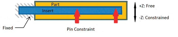
Figure 1: Pin supports of cores require one-sided constraints for accurate core-shift analysis.
Figure 1: Pin supports of cores require one-sided constraints for accurate core-shift analysis.
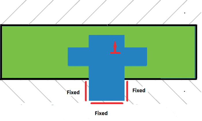
Figure 2: The insert (blue) can move up into the plastic part but is blocked from downward movement by the mold surface. One-sided constraints are needed for such parts.
Figure 2: The insert (blue) can move up into the plastic part but is blocked from downward movement by the mold surface. One-sided constraints are needed for such parts.
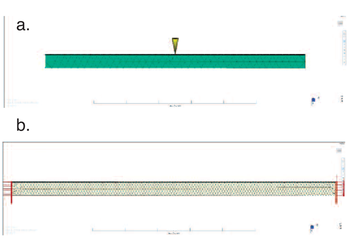
Figure 3: Case study (from top): a) molding, b) core
Figure 3: Case study (from top): a) molding, b) core

Figure 4: Flow front propagation; fixed support of the core
Figure 4: Flow front propagation; fixed support of the core
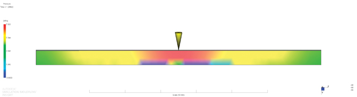
Figure 5: Pressure in the middle of the packing phase; fixed support of the core
Figure 5: Pressure in the middle of the packing phase; fixed support of the core
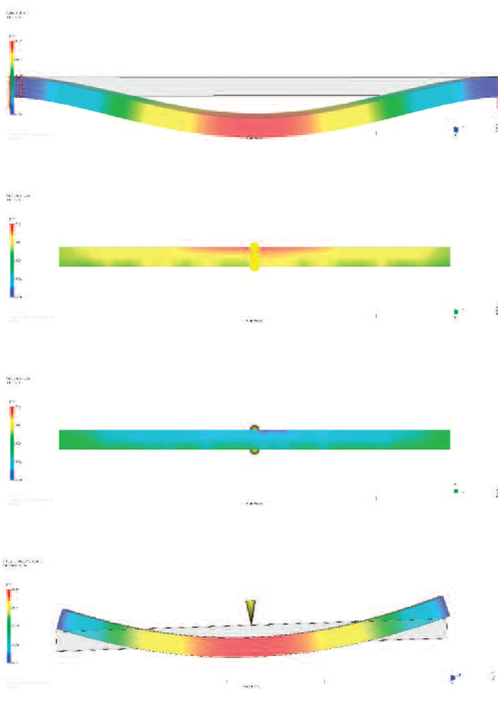
Figure 6: Simulation results for the fixed core (from top): final deformation of the core; thickness of the moldings, injection side; thickness of the moldings, opposite side; and warpage of the moldings
Figure 6: Simulation results for the fixed core (from top): final deformation of the core; thickness of the moldings, injection side; thickness of the moldings, opposite side; and warpage of the moldings
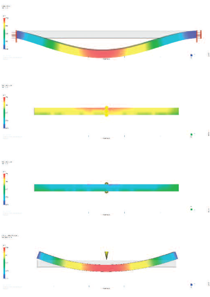
Figure 7: Simulation results for the one-sided constraints of the core (from top): final deformation of the core; thickness of the moldings, injection side; thickness of the moldings, opposite side; and warpage of the moldings
Figure 7: Simulation results for the one-sided constraints of the core (from top): final deformation of the core; thickness of the moldings, injection side; thickness of the moldings, opposite side; and warpage of the moldings
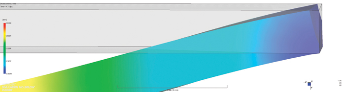
Figure 8: One-sided constraints allow some separation between the mold wall and the core (predictions for final core displacements; one-sided constraints on the core).
Figure 8: One-sided constraints allow some separation between the mold wall and the core (predictions for final core displacements; one-sided constraints on the core).
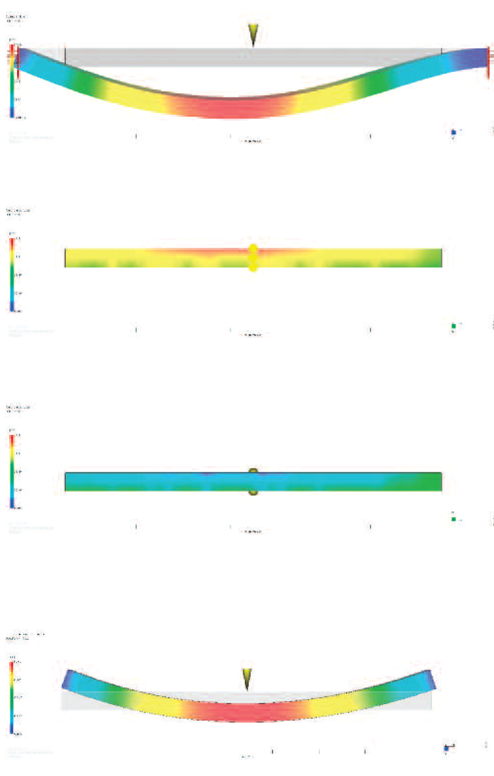
Figure 9: Simulation results for the one-sided constraints with a gap (from top): final deformation of the core; thickness of the moldings, injection side; thickness of the moldings, opposite side; and warpage of the moldings
Figure 9: Simulation results for the one-sided constraints with a gap (from top): final deformation of the core; thickness of the moldings, injection side; thickness of the moldings, opposite side; and warpage of the moldings
Core shift can be defined as the spatial deviation of the position of the mold cores and inserts caused by the imbalance of polymer pressure during injection molding. The resulting change of the boundary conditions in turn affects the filling pattern and packing pressure distribution and may create residual pressure at the end of cooling (over-packing) and deviations of the molding thickness. The final result may be inferior quality of the molded parts. It is a pervasive problem in the manufacturing of thin-walled containers.1-8
In previous work,9 we presented an algorithm for predicting the core shift effects by mold filling simulation. The algorithm assumes simple (two-sided) geometrical constraints for the cores that fully remove some translational degrees of freedom of the cores. It means that if a constraint prevents displacements in some direction, then this constraint also prevents displacements in the opposite direction. Still, many injection molds include a special boundary condition of “constraint in one direction, but free movement in the opposite direction” that we will call a “one-sided constraint.”
A few typical cases from customer supports are shown in Figures 1 and 2. In Figure 1, the insert is supported by several pins and therefore the constraints at the pin-supported points are one-sided. In Figure 2, the blue insert can move into the plastic part (green), but it is blocked from the opposite direction by the mold surface. To properly predict core shift on such molds, we need to handle one-sided constraints, which is the aim of the present work.
Theory
We predict melt pressure through the cavity and runners using a numerical solution of the low-Reynolds number momentum equation:
![]() (1)
(1)
together with a rheological equation:
![]() (2)
(2)
energy equation:
![]() (3)
(3)
and mass-conservation equation:
![]() (4)
(4)
where:
![]() = shear stress,
= shear stress,
![]() = pressure,
= pressure,
![]() = shear rate,
= shear rate,
T = temperature,
t = time,
v = melt velocity,
a = thermal diffusivity,
![]() = shear heating,
= shear heating,
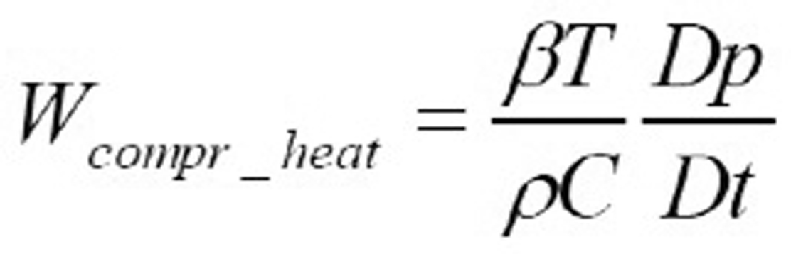 = compression heating,
![]() = polymer density,
= polymer density,
and Sρ is an additional polymer velocity source term for the nodes on the mold core/polymer melt interface that describes movement of the mold core:
![]()
where u is the deformation of the interface and n is the direction of the normal to this surface.
To solve fluid dynamics Equations 1-4, we use Hele-Shaw approximation using triangular elements.10 For chunky moldings, we solve Equations 1-4 in true 3-D formulation using 4-node tetrahedral elements.11
The melt pressure p creates additional surface forces f acting on the boundary of the core:
![]() (5)
(5)
These forces would cause deformation of the core u that we can find using momentum equations inside the core:
![]() (6)
(6)
together with Hooke’s law:
![]() (7)
(7)
and boundary conditions:
![]() (8)
(8)
In Equations 5-8, σ is stress, ε is strain, n is a normal vector for polymer-core interface, and C is the mold material compliance.
The supports for the cores are implemented as springs; there an additional nodal force reaction freaction is proportional to the deflection of the node u:
![]() (9)
(9)
In Equation 9, Kis the spring elasticity andu0is the equilibrium position of the node. If the support fixes deflection component ui, we select the corresponding component of the spring elasticity tensor Kiito be a large value Kfixed(much higher than the elasticity of the core itself); if the support left deflection component ui to be free, we choose the elasticity Kiito be zero. For elastic support, appropriate values for spring elasticity Kallow to accurately take into account movement of the support. The off-diagonal terms of the tensor Kare used to describe tilted support when movement in some directions is constrained and in other directions is free.
Usually the equilibrium positions of constrained nodes u0are set to zero; non-zero equilibrium positions can be used to simulate prescribed displacements on the node constraint or pre-stressed support (e.g. clamping force).
For one-sided constraints, spring elasticity and the equilibrium position become dependent upon deflection of the constrained node u. For each component of the deflection, we consider three types of the constraints:
- (A) movement in positive direction is limited up to some value u+, while movement in negative direction is free;
- (B) movement in positive direction is free, while movement in negative direction is limited down to some value u-; and
- (C) movement in positive direction is limited up to some value u+, while movement in negative direction is limited down to another value u-.
For the one-sided constraints of type (A) we can select effective spring elasticity Kand equilibrium position u0 as:
![]() (10)
(10)
Similarly for the one-sided constraints of type (B):
![]() (11)
(11)
And for the one-sided constraints of type (C):
![]() (12)
(12)
We solve Equations 5-9 using three-dimensional models for mold cores represented by 4- and 10-node tetrahedral elements.
As described in our previous work,9 we discretize elasticity Equations 6-8 using three-dimensional models for mold cores represented by 4- and 10-node tetrahedral elements, assemble them together with equations describing support 9-12, and solve the system simultaneously with flow Equations 1-5. The resulting software allows prediction of core shift with one-sided constraints during injection molding of thermoplastics.
Case Study
As an example of the simulation results, we use the core shift of a square polypropylene 5×5×80-mm tube of 1-mm thickness injected from the middle (shown by Figure 3a). The molding is modeled using mid-plane triangular elements. The core for this molding is simply a rectangular 4×4×100-mm steel piece supported from both sides (see Figure 3b).
We consider three very similar types of support for the core:
- Fully bonded to the mold (fixed support): this support will be difficult to implement.
- One-sided supports limited by the mold surface: they are much easier to implement, but they are less stiff. We assume that there are no gaps between the cores and the mold surface at the point of support.
- One-sided supports limited by the mold surface but with a gap of 0.5 mm in the Z direction on the left constraints. Small gaps between the core and mold can be expected. The gap makes the mold even less stiff as it makes rotation even easier.
Since the injection is on a side of the tube, there is an imbalance in flow fronts and pressures between the injection and the opposite sides of the cavity (see Figures 4 and 5); these are causing deformation of the core away from the injection side that additionally amplify the imbalances. The result is significant deformation of the cores and a strong difference between the wall thickness on the injection and the opposite sides of the moldings.
Fixed core support
Predictions for the fixed core are shown on Figure 6. There are significant changes of the wall thickness going from the nominal 1 mm up to 1.5 on the injection side and down to 0.3 mm on the opposite side, which causes a warpage of 1.4 mm.
One-sided constraints of the core
Predictions for the one-sided constraints of the core are shown on Figure 7. The increased deformation of the core caused even larger changes in the wall thicknesses that now vary between 0.12 and 1.77 mm. Warpage also increases up to 1.5. The difference is caused by one-sided constraints allowing some separation between the mold wall and the core, as shown on Figure 8. This separation allows the core to rotate slightly at the supports, thus making the supports weaker.
One-sided constraints with a gap
Predictions for the one-sided constraints with a gap are shown on Figure 9. The gap between the core and the mold makes the rotation of the core at support easier, and so it additionally weakens the supports. The wall thicknesses now vary between 0.08 and 1.8 mm. Warpage also slightly increases.
Discussion of the case study
The case study clearly shows a significant effect of one-sided constraints of the core on predicted quality of moldings, even for the cases very similar to two-sided constraints. While we can imagine that predicted for the fixed core constraints lowering down of the minimal wall thickness to 0.3 mm would be acceptable for some moldings, predicted for the one-sided core constraints lowering down of the minimal wall thickness to 0.08-0.12 mm would be clearly unacceptable. Thus, the correct specification of one-sided constraints is essential for a correct core-shift analysis.
Conclusions
A working algorithm for considering one-sided constraints of cores and inserts during mold filling analysis was presented. One-sided constraints significantly affect predictions of core shift, even for the cases very similar to two-sided constraints.
References
- Shepard, T. A., O’Connell, M., Powell, K., and Charwinsky, S. “Minimizing Coreshift in Injection Molded Containers,” Plastics Engineering, 52, 2, 27-29 (1996).
- Shepard, T. A., O’Connell M., Powell, K., and Charwinsky, S. “Mechanism for Core Shift in Injection Moulded Containers,” Proceedings of Medical Design & Manufacturing, p.107-113 (1995).
- Overbeeke, J., “High Speed Injection,” SPE ANTEC Proceedings, 2, 557-562 (1993).
- Dagniaux S. D. J., “Tool Design for Injection Moulding of Polypropylene Thin-Walled Containers,” SPE ANTEC Proceedings, 290-293 (1979).
- Rose, G. E., “Core-shift, Coupling Moldflow and ABAQUS,” Moldflow User Group, podium presentation (2003).
- Hunkar, N. J., and Watkins, B. H., “Preform Core Transducer,” High Performance Blow Molding Conference proceedings, 117-128 (1995).
- Leo, V. and Cuvelliez, C., “Effect Of Packing Parameters, Gate Geometry And Mould Elasticity On the Final Dimensions of a Moulded Part,” Polymer Eng. Sci., 36, 1961-1971 (1996).
- Baaijens, F.P.T., “Calculation of Residual Stresses in Injection Molded Products,” Rheol Acta, 30, 284-299 (1991).
- Bakharev, A., Fan, Z., Costa, F., Han, S., Jin, X., and Kennedy, P. “Prediction of Core Shift Effects Using Mold Filling Simulation,” SPE ANTEC Proceedings (2004).
- Kennedy, P. Flow Analysis of Injection Molds, Hanser Publishers (1995).
- Talwar, K., Costa, F, Rajupalem, V., Antanovski, L. and Friedl, C. “Three Dimensional Simulation of Plastic Injection Molding,” SPE ANTEC Proceedings, 1, 563-566 (1998).