
Guidelines for Part & Tool Design for Molding Rigid Clear Materials
Stiff-flowing polystyrenes, acrylics, and the newest copolyesters have molding limitations that must be accounted for
Previous Article Next Article
By Mark Rosen
Corex Design Group Inc., Franklin Lakes, New Jersey, USA
Guidelines for Part & Tool Design for Molding Rigid Clear Materials
Stiff-flowing polystyrenes, acrylics, and the newest copolyesters have molding limitations that must be accounted for
Previous Article Next Article
By Mark Rosen
Corex Design Group Inc., Franklin Lakes, New Jersey, USA
Guidelines for Part & Tool Design for Molding Rigid Clear Materials
Stiff-flowing polystyrenes, acrylics, and the newest copolyesters have molding limitations that must be accounted for
Previous Article Next Article
By Mark Rosen
Corex Design Group Inc., Franklin Lakes, New Jersey, USA
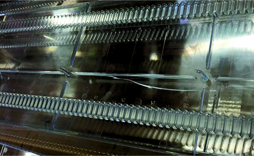
Figure 1: A long clear part with issues of part cracking near the gate at mold-open (the issue was that ribs near the gate had too little draft).
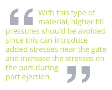
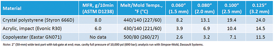
Table 1: Flow Lengths (in Inches) for Various Wall Thicknesses (0.060-0.125"), for a Simple, Rectangular Part
Table 1: Flow Lengths (in Inches) for Various Wall Thicknesses (0.060-0.125"), for a Simple, Rectangular Part
Table 1: Flow Lengths (in Inches) for Various Wall Thicknesses (0.060-0.125"), for a Simple, Rectangular Part
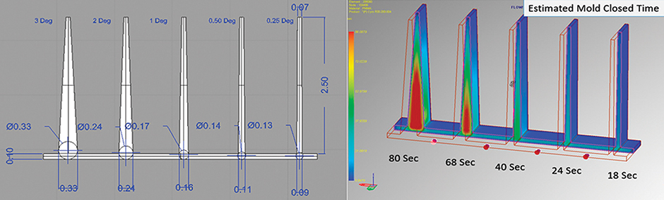
Figure 2: Study of draft angle (left) vs. cooling time (right) vs. for 2.5” (63.5-mm) tall rib, 0.070” (1.8-mm) wide at the top (the material was Evonic Cyro R-30 impact-modified acrylic; analysis was run with Simpoe-Mold, Dassault Systems).
Figure 2: Study of draft angle (left) vs. cooling time (right) vs. for 2.5” (63.5-mm) tall rib, 0.070” (1.8-mm) wide at the top (the material was Evonic Cyro R-30 impact-modified acrylic; analysis was run with Simpoe-Mold, Dassault Systems).
Figure 2: Study of draft angle (left) vs. cooling time (right) vs. for 2.5” (63.5-mm) tall rib, 0.070” (1.8-mm) wide at the top (the material was Evonic Cyro R-30 impact-modified acrylic; analysis was run with Simpoe-Mold, Dassault Systems).

[Ed. note: The author can be reached at mrosen@corexdg.com or U.S. 201-970-9188; learn more about his services at the end of this article.]
The injection molding of rigid clear materials can often be a challenge due to their stiff-flowing nature and somewhat brittle mechanical properties. These materials can range from low-cost crystal polystyrene to higher-performance materials such as impact-modified acrylics or copolyesters. I’m often asked to troubleshoot molds for these clear, stiff materials, facing issues such as poor surface cosmetics, cracking at ejection (e.g., Figure 1), and underfilled regions of the part.
Although there are many rigid clear materials, the goal of this article is not to discuss the range of material options but to highlight some of the general requirements for part and tooling design and processing. Many of these materials have common traits in that they are relatively stiff-flowing, can degrade and off-gas when overheated or over-sheared, have a lower percent elongation at break and lower notched-Izod values, and can sometimes stick to hot polished surfaces.
Whenever troubleshooting parts that are molded of these materials, I first focus on the following questions, which will be discussed in this article, along with some general rules for good part and mold design:
- Fill pressure: Higher fill pressures can result in increased molded-in stresses and more difficult ejection. What is the nominal wall and flow length of the part? Has a filling analysis been done to calculate the expected fill pressure?
- Runner and gating: Is the runner and gating optimized for clear rigid materials? Higher fill pressures and poor cosmetic issues are often due to poor runner/gating design and gate location.
- Draft and polish: Does the part have adequate draft on vertical walls, and are the surfaces properly polished? Rigid clear materials can crack at mold-open or part ejection.
- Venting: How is the tool vented? Some clear materials can be a bit gaseous, thereby increasing the need for good venting.
- Mold Cooling: Many clear materials have a tendency to stick to hotter mold surfaces. This can be made worse with slender tool components which may flex during molding.
Fill Pressure
When running these materials, establishing the correct pack profile can be tricky. Higher injection pressures may be needed to overcome restrictive gating, longer flow lengths, and poor venting. Raising the melt temperatures to lower the fill pressures can cause issues with many clear materials. At too-high a temperature and/or extended residence times, the surface finish of the part can become worse and the material can become more gaseous. This can make part-sticking issues worse.
In an effort to reduce sticking of the part, reducing the pack/hold pressure and time can result in a part with “wavy” surfaces and/or increased warpage. The use of larger gates are recommended since this will reduce the fill pressures and allow for longer pack times, which is preferred over high pack pressures and shorter pack times required when thinner gates are used.
Many clear materials are stiffer-flowing materials with melt flow rate (MFR) values in the range of 3 to 8 g/10 min. (ASTM D1238). Also, being amorphous in nature, these materials require longer pack times. With this type of material, higher fill pressures should be avoided since this can introduce added stresses near the gate and increase the stresses on the part during part ejection. For these stiffer-flowing materials, as a general rule, it’s recommended to have a part design and gate location such that total pressure drop does not exceed around 15,000 psi (1030 bar). For design purposes, this results in a cavity pressure drop limit of around 10,000 psi (690 bar) and runner loss of no more than 5000 psi (340 bar). These pressure drops should confirmed by a 3-D mold-filling analysis by a skilled user.
In Table 1, a simple rectangular part (cavity only) was analyzed by Simpoe-Mold (Dassault Systems) using a tetrahedral 3-D mesh to test the fill pressure at various thicknesses for three different clear materials. A pressure limit of 10,000 psi (690 bar) was used for the cavity fill pressure. Note that the higher performance impact-modified acrylic and copolyester are stiffer flowing than the crystal PS.
Runners & Gating
For clear parts with optical surfaces, the use of cold runners with wide gates located on the side of the part is preferred over hot runners with gates in the middle of the part. This is because gates located in the middle of the part are more prone to stress marks, plus create concerns with a visible gate vestige. A combination of hot and cold runners can also be successfully used with side tab gates. For larger parts, sometimes center gates must be used to reduce the flow length. If so, larger valve gates or “hot sprue gate”-type tips are recommended.
First, try to use the minimum number of gates which will fill the part at a reasonable pressure. This results in a simpler flow pattern with fewer weld lines and flow hesitation. Run mold-fill analysis to optimize gate location, number of gates, and runner sizes. Gate in thicker wall section of the part, and try to locate gates so there’s a flat flow pattern at end of fill; this results in less acceleration of the melt front at the end of fill, which improves venting and part cosmetics. Other recommendations include:
- With cold runners, use full round runners no thinner than the thickness of the part and a minimum of 3/16” (4.8 mm) diameter. Design runners for pressure drops no greater than 4000 psi (280 bar). Run flow simulation to confirm pressure drops and gating.
- For these stiffer, more brittle materials, two-plate mold cold-runner designs are preferred vs. three plates.
- For best surface finish, use wide gate designs (a width of at least 1 ½- to 2-times the runner diameter; for thicker parts, the width can be as large as 2-3 inches (51-76 mm)). Use gate thickness of at least 60-70% of wall thickness. Runners should run perpendicular to the gate with a cold slug length of 1 ½- to 2-times runner diameter. This layout helps reduce jetting and surface defects.
- If possible, try to locate gates adjacent to the vertical wall to prevent jetting flow.
- For cold runners, use a hot tip or larger sprue (min. 3/16” (4.8-mm) diameter at top) with added draft (2 to 3 degrees recommended) to prevent sticking during mold-open.
Draft & Polish
For these materials, suppliers will typically recommend that parts be designed with a minimum draft angle of 1 to 3 degrees to reduce sticking during mold-open and part ejection. However, with taller ribs, using these larger draft angle recommendations can result in wall sections at the base of the ribs which are too thick, resulting in long cycle times, along with surface sink or voids.
In Figure 2, it can be seen that for a 2 ½” (76-mm) tall rib with a 0.070” (1.8 mm) top thickness, using a draft angle of 1° results in a reasonable estimated mold-closed time. This compares to uneconomical estimated mold-closed times of 68 and 80 seconds for 2° and 3°, respectively.
The following are some general guidelines for draft and polish:
- When possible, design parts so the parting line of the mold is at the bottom of the side walls. This allows for the use of parting line vents or full-perimeter venting at bottom or a stripper plate.
- For taller standing features and ribs buried in the tool, a 1° draft is recommended to balance the required draft angle for part ejection vs. cycle time.
- For holes and short ribs near the gate it may be necessary to use more draft (3° or more) to prevent sticking. Also, add a minimum of a 0.020” (0.5 mm) radius at the base of the wall to prevent cracking.
- For highly polished large flat surfaces, often air poppets are needed in the mold to break the vacuum seal.
- Always polish in line of draw for ribs, and make sure vertical surfaces are clean with no surface damage. Even small undercuts can cause jamming with these materials.
- Clear parts can often stick on the front half of the mold during opening. This needs to be considered during the mold design, for the possible use of spring-loaded pins on the front half of the mold.
Venting
Good venting is key to molding clear parts. Molds with compromised venting will require slower fill time and higher fill pressures and be more prone to surface defects (see also the article “Good Venting” in the June 2015 Plastics Engineering for an overview of venting recommendations).
First, run a flow simulation to locate gates to minimize air traps, severe weld lines, and converging flow fronts at end of fill. And....
- Use active vents whenever possible, since these vents tend to be self-cleaning. Full perimeter venting is preferred when possible. See material supplier data for recommended vent depths (typically around 0.001 to 0.002” (0.03-0.05 mm)). In addition, make sure to vent runners to reduce gas buildup near gates.
- For parting line vents, keep the land of the vents short, at 0.040 to 0.100” (1.0 to 2.5 mm), with dump depths stepped down by 0.015 to 0.040” (0.4-1.0 mm). Make sure at least 25% of the parting line is vented and make sure the dump vents to atmosphere. Try to keep the path to atmosphere as short as possible to help reduce gas buildup.
- When static vents are used (mold inserts or non-moving pins), use short land lengths (0.040 to 0.060” (1.0-1.5 mm)) and polish vents in line of draw. In some cases, static vents can be designed with an air-pressure circuit to blow positive air pressure to clean the vent at mold open. Try not to use mold release with static vents.
Cooling
Many clear materials have a tendency to stick to hot mold surfaces, so the mold should have good cooling to minimize hot spots. Try to avoid part designs requiring long slender cores in the mold which will run hotter. Also, try to avoid tall ribs or slender cores on the front half of the mold, as these can result in the part sticking at mold open. With box-shaped parts, if possible, move the ejector pin locations to allow cooling of inside corners of the parts. With cold runner layouts, larger cold sprues should be used, and adding water in the mold to cool the sprue is recommended.
Summary
In summary, the molding of stiff clear materials can sometimes make it challenging to get acceptable part surface cosmetics and to not damage parts during mold-open and ejection. In this article, we discussed some rules to follow for part and tool design to help with these challenges.
To improve the odds of success, it’s recommended to include in the budget a detailed part and mold design review by a broadly skilled review team with expertise in materials, part design, tooling, and processing. This should also always include a filling analysis (by a skilled analyst using a higher-end analysis program). Parts molded with these clear rigid materials often have delays in sampling approvals, with expensive tooling changes often due to rushed schedules, lack of up-front engineering review, and attempts to save money with lower-cost tooling.

About the author… Mark Rosen is founder of Corex Design Group (www.corexdg.com), an award-winning plastics consulting firm consisting of plastics industry veterans available to assist companies with design, engineering, analysis, and technical marketing. He can be reached via e-mail at mrosen@corexdg.com or by phone at +1 201-970-9188.