
Cold Runner Design: Sizing Up Your Runner System
Designing runners for multi-cavity injection molds is no straightforward process
Previous Article Next Article
By David A. Hoffman
American Injection Molding (AIM) Institute, Erie, Pennsylvania, USA
Cold Runner Design: Sizing Up Your Runner System
Designing runners for multi-cavity injection molds is no straightforward process
Previous Article Next Article
By David A. Hoffman
American Injection Molding (AIM) Institute, Erie, Pennsylvania, USA
Cold Runner Design: Sizing Up Your Runner System
Designing runners for multi-cavity injection molds is no straightforward process
Previous Article Next Article
By David A. Hoffman
American Injection Molding (AIM) Institute, Erie, Pennsylvania, USA
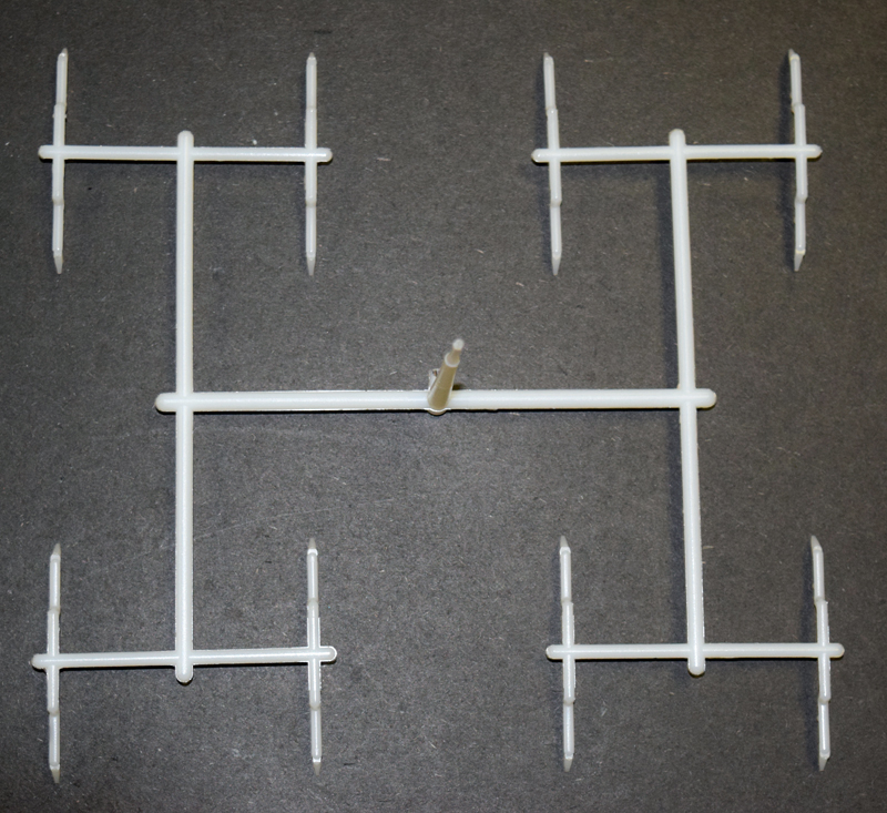
Figure 1: A 16-cavity, geometrically balanced mold layout.
Figure 1: A 16-cavity, geometrically balanced mold layout.
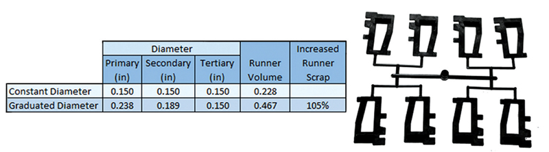
Figure 2: Different runner sizing approaches for the eight-cavity mold shown.
Figure 2: Different runner sizing approaches for the eight-cavity mold shown.
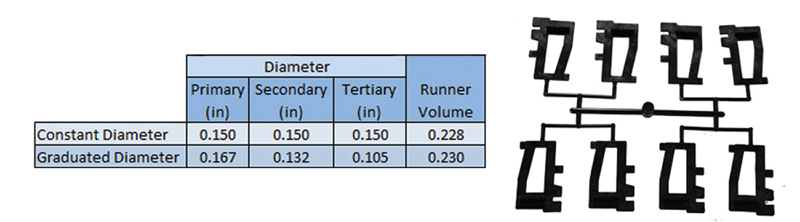
Figure 3: A graduated runner that has the same runner volume as the constant-diameter runner.
Figure 3: A graduated runner that has the same runner volume as the constant-diameter runner.

The topic of runner sizing always comes up during our plastics education courses at the AIM Institute. Everyone wants a magic formula for sizing every runner for every mold, regardless of machine capabilities, pressure to fill the part, cycle-time requirements, and packing. There is much confusion in the industry about this topic, so let’s take a look at various thought processes for sizing cold runner systems.
Consider the 16-cavity, geometrically balanced mold layout shown in Figure 1. Think about the questions you would ask yourself when trying to determine how to size the runner system. Then consider this question: “Should each diameter of each leg of the runner system be the same diameter, or should the diameters of each leg change whenever the runner splits/branches?” The typical response to this question is that the diameters should change at every branch. The next question to answer then is “Why?” Typically I get two responses to this question: either a blank stare or “Well, that’s the way we always have done it.”
There are other explanations we’ve heard over the years about why we think we need to change runner sizes at every branch. These include: to maintain a constant shear rate in the runner, maintain a constant velocity in the runner, maintain a constant pressure drop per unit length in the runner, or minimize runner volume. (Note: for discussion purposes we’ll call a geometrically balanced runner that uses different sizes at each progressive branch a “graduated” runner.)
The Science behind the Theory
Let’s presume that you want to use a graduated runner design. Now the discussion naturally leads into how to determine which diameters you should use. Our industry has several methods for determining the sizes of a graduated runner, including standard formulas, rules of thumb, mold filling simulation, and “whatever the next cutter size is.” Each method has its own scientific-sounding theory behind it (except maybe the cutter size method), and each method may work for a given scenario. But we need to understand the science (or lack of science) behind each theory and determine if it’s important to the part, material, and/or process.
As an example, this formula is used by many designers in our industry to size runner systems:
![]()
In fact, some simulation software companies will even reference this formula, if for some reason simulation cannot be used to engineer the runner system. (The d stands for the runner diameter at each section of the runner, and N stands for the number of branches at the split. For example, if the feed runner splits in two directions, then N = 2.)
The science behind this formula relates to shear heating and thermal cooling. However, an interesting outcome of this formula is that it provides runner sizes where each leg of the runner will experience the same shear rate. This is one of the theories mentioned earlier, and this may sound like a good thing, but you have to ask some more questions:
Is having the same shear rate in each runner leg important to you, considering the shear rate is probably not the same everywhere within the part?
- What material are we molding?
- How much available pressure does the molding machine have?
- How much pressure drop through the runner system and part is acceptable?
And so on.
To further explore this, consider only the material you’re molding. The formula above would provide you with the same runner sizes regardless of whether you’re molding the part out of a polypropylene material or a polycarbonate. Does that sound right to you?
Graduated or Constant-Diameter Runners?
As you can see, it’s important to understand the methods you may be using to size your graduated runner design. To throw a curve-ball into the discussion, now consider making the runner branches all the same size. Many of you are probably saying: “Who would ever do such a thing? You always have to step the runner sizes.” But please bear with me.
Figure 2 shows two different runner sizing approaches for the eight-cavity mold shown. In this case study, the minimum diameter of 0.150” (3.8 mm) was selected to help ensure good packing of the part. Therefore, if that is our minimum runner size, then the graduated runner branches become larger as they progress back toward the sprue. The result is that the graduated runner has roughly twice as much material volume than the constant-diameter runner design. In addition, the graduated runner may also increase the overall cycle time due to the size of the primary runner.
Another design approach to consider would be to utilize a graduated runner that has the same runner volume as the constant-diameter runner. This is shown in Figure 3. Now we have not wasted any additional material with the graduated runner as we did in the previous scenario. But when looking closer at the designs, it appears that the graduated runner system would still need a longer cooling time, along with creating a potential packing problem due to the smaller tertiary runner diameter.
All of these considerations tend to frustrate people, and so the next question they ask is: “Which runner sizing technique works on every mold, material, and part?” The answer: None. When sizing a runner system you need to ask yourself: What’s important to you? Below are five common replies to that question.
- Material volume
- Cycle time
- Maximum injection pressure
- Packing
- Degradation
Typically the replies are not only one specific answer, but rather a combination of two or three of them. But if you can prioritize your answers, it will serve as your guide on how best to size the runner system to meet your objectives. You may find out that a graduated runner is best for one mold, but a constant-diameter runner is best for the next mold; and yet a runner system where the sizes only change on some runner legs may be best for another mold. This article only scratches the surface of the science behind runner sizing techniques. If you would like to learn more about this topic, please visit www.aim.institute.
About the author… David A. Hoffman is senior instructor, Plastics Education & Training, for the American Injection Molding Institute and has worked as a part and mold designer, process engineer, and engineering manager for various companies, in addition to working as technical sales manager for Beaumont Technologies, Inc. Contact him at U.S. 866-344-9694 or dhoffman@aim.institute.