Tilting Technologies and GWDS: Novel Solutions for Annular Dies
Previous Article Next Article
By Heinz Gross
Dr. Gross Kunststoff-Verfahrenstechnik, Rossdorf, Germany
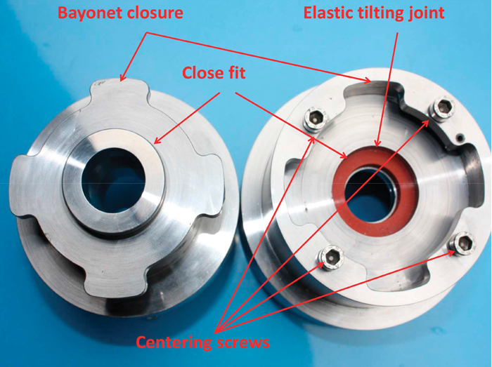
Figure 1: Disassembled tilting die showing the special bayonet closure and the elastic tilting joint

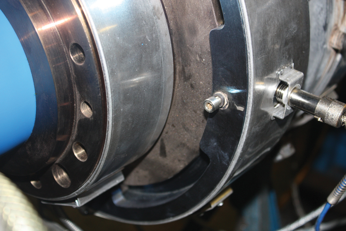
Figure 2: Tilting die in operation showing one of the small axially arranged adjusting screws having a special fine pitch for a sensitive tilting of the die
Figure 2: Tilting die in operation showing one of the small axially arranged adjusting screws having a special fine pitch for a sensitive tilting of the die
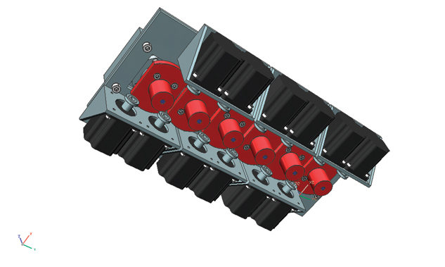
Figure 3: Unit to retrofit the tilting technology to an existing six-cavity head having twelve stepper drives to tilt every die individually
Figure 3: Unit to retrofit the tilting technology to an existing six-cavity head having twelve stepper drives to tilt every die individually
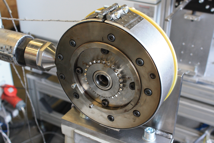
Figure 4: Side-fed tube head having an elastic tilting joint to tilt the die and to shift the die axially in regard to the mandrel, and a Flex Ring sleeve to sensitively reduce existing non-symmetric thickness differences over the circumference of the tube
Figure 4: Side-fed tube head having an elastic tilting joint to tilt the die and to shift the die axially in regard to the mandrel, and a Flex Ring sleeve to sensitively reduce existing non-symmetric thickness differences over the circumference of the tube
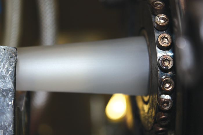
Figure 5: Tube die with radially arranged screws to optimize the flow-channel gap between the Flex Ring sleeve and the mandrel to reduce the thickness tolerances in the tube
Figure 5: Tube die with radially arranged screws to optimize the flow-channel gap between the Flex Ring sleeve and the mandrel to reduce the thickness tolerances in the tube

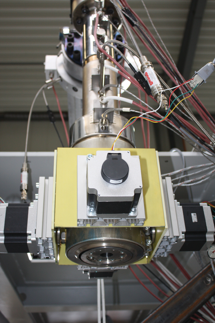
Figure 6: Novel GWDS blow-molding head which allows for a further improvement of the thickness distribution of blowmolded parts
Figure 6: Novel GWDS blow-molding head which allows for a further improvement of the thickness distribution of blowmolded parts
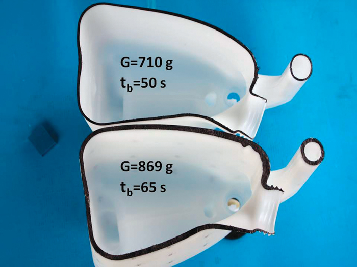
Figure 7: Wall thickness distribution, weight (G), and blowing or cooling time (tb) of tanks that have been produced conventionally (shown at bottom) and with GWDS technology (at top)
Figure 7: Wall thickness distribution, weight (G), and blowing or cooling time (tb) of tanks that have been produced conventionally (shown at bottom) and with GWDS technology (at top)

It is state of the art to produce pipes or tubes having the same diameter but a slightly different wall thicknesses without changing the die. In order to achieve different wall thicknesses, the haul-off speed is simply changed, but as a consequence, the molecular orientation also changes with different wall thicknesses. This is often not desired, as it leads, for example, to varying shrinkage values of the final products.
An optimum die gap is particularly advantageous if the molecular orientation between die and calibrating unit is to be kept low, in order, for example, to minimize shrinkage. It would naturally also be desirable if this additional option in process engineering is not achieved at the expense of a far more complex head construction—and also if the ease of operation and maintenance is not impaired. Tilting technology, developed to allow for a more accurate and specific centering of a head, has created new boundary conditions for being able to adjust the die gap easily.1,2,3
Tilting Technology
With tilting technology, heat-resistant (up to 300°C) elastomeric seals are used to seal the gap between the head and the die (see Figure 1). The die can now be tilted, instead of being shifted, to center the die in relation to the mandrel.
Tilting offers a whole range of interesting benefits, compared with conventional metallic seals. Since the die no longer has to be shifted back and forth, a tight fit can be created between die and head so that the die can only be installed centrically. The pre-centering of the die that was necessary to-date after cleaning a head can thus be totally eliminated. In order to ensure the reproducible compression of the tilting seal necessary for reliable sealing, the die has a simple bayonet fitting. Eccentric differences in thickness of the extruded products can be reduced by tilting the die. This is currently performed in a transitional phase using axially arranged adjusting screws (Figure 2).
The final goal is to enable a motorized solution so that the centering can be performed from the control cabinet of the extrusion line. This immediately allows for a more precise centering, and opens up the possibility that an optimized position, once found, can be exactly reproduced at any time. When restarting the head after it has been cleaned, the die can be immediately brought back exactly to the same position that it possessed during the last production.
In extrusion blow molding, a motorized adjustment system allows the die to be tilted dynamically—even during the discharge of the parison, for example, in order to take account of the different stretch ratios on the inside and outside of the curve when producing curved tubes and pipes (Figure 3). When tilting the die, the elastomeric seal is simply compressed slightly more on that position where the die gap is to be reduced. The gap of the flow channel on the opposite side is accordingly in the same time increased by the same amount.
But tilting technology has not only overcome the disadvantages associated with the conventional centering solution, it has also led to a simplification of the construction of annular heads. This also leads to a reduction in the fabrication costs for annular heads. Once the concern generally prevailing among experts has been overcome—that an elastomeric seal should not be integrated into the flow channel of an extrusion head—it was a logical next step to exploit the elasticity of the seal to also adjust the die as a whole relative to the head. And if additionally the principle is then breached that a tube die has to have a parallel discharge zone at the end of the flow channel, the way is open for an adjustment of the die gap. This is achieved without increasing the complexity of head construction compared to the generally known solutions currently used in extrusion blow molding.
Although it has undisputed process engineering drawbacks,4 it is still state-of-the-art in extrusion blow molding to use heads with a conical mandrel and conical die at the die outlet in order to be able to adjust the die gap. For this, either the mandrel or the die is shifted axially over a given distance. A certain leakage has to be accepted, as the moving head section has to be shifted in a bore with a fitting allowance. If the gap of a tube head is to be changed, it is sufficient for only the mandrel to have a conical form while using a cylindrical die. The possible adjustment range of the gap is then dependent on the cone angle of the mandrel end and on the travel distance that can be achieved with the additional compression of the tilting seal.
Axially Adjustable Dies and GWDS
For tubes with the same or at least a similar outside diameter, the bandwidth of desired wall thicknesses is generally fairly small. In practice, travel distances of just a few millimeters are therefore sufficient in order to be able to achieve the required gap variation. If the tilting seal is designed slightly thicker, the seal can be compressed further, starting from the preload necessary to achieve the sealing effect. This can be steplessly achieved using a simple threaded ring.
Figure 4 shows a tube head of this type with integrated tilting joint and die gap adjustment. The die is tilted by means of four axially arranged adjusting screws in the face of the die which act directly on the flanged collar of the die. Between the clamping screws (with which the head cover is attached to the head) and the centering screws is a threaded ring to change the size of the flow-channel gap at the exit of the die. In addition, the head also has a Flex Ring sleeve.5Adjusting screws arranged over the circumference of the die allow limited localized adjustment of the flow-channel gap in order to be able to minimize asymmetric thickness fluctuations. The improved and more precise centering possibility and the localized changing of the flow-channel gap using the Flex Ring sleeve thus enable thickness tolerances to be attained in the tube which were not achievable previously.
Figure 5 shows the special tube head in operation. The newly designed head also sets standards when it comes to the ease of maintenance. Despite the gap adjustment feature, the head can be completely cleaned without having to be removed from the extruder flange. After loosening the bolts with which the head cover is fastened to the main housing of the head, the cover can be removed and the whole flow channel of the head is accessible for cleaning. During this, the main housing remains flanged to the extruder.
Tilting technology had for a certain time only limited use. The elastic tilting joints can only be used up to operating temperatures of 300°C. Furthermore, the wear resistance of the elastomeric blend is not sufficient for processing compounds with abrasive constituents. However, these limits could be overcome with an alternative metallic tilting seal; this then even allows for a much wider movement of the die in regard to the mandrel.
Figure 6 shows a recently developed advantageous GWDS (Gross Wanddickensteuerung)7 head for extrusion blow molding, which has a metallic tilting joint. Instead of conventional conical flow channels, GWDS dies use cylindrical ones at the end of the die.4 Operated by four stepper drives, the die shown in Figure 6 can be tilted in order to center it. But at the same time it can be shifted axially by 20 mm in order to change the relative position between the die and the mandrel. The big realized adjusting path is of importance, as the GWDS technology requires longer adjusting paths than conventional blow molding dies.
Compared to well-established conventional production methods, GWDS dies open up the potential to further improve the wall thickness distribution of every blow molded part that is produced worldwide. For packaging applications, the GWDS technology helps to significantly improve the thickness distribution, especially for smaller blow-molded bottles. As an example, the minimum thickness of a 500-mL PE bottle could be increased by 17%, enlarging the top load the bottle can withstand by 22%, compared to the state-of-the-art conventional production method.
Also, in the field of technical hollow parts, formidable improvements in thickness distribution are possible. Figure 7 shows the comparison between a small fuel tank that has been produced using a conventional technique and one produced by GWDS technology. To reach this convincing result, a conventional machine with a solid die and a solid mandrel was used. It’s impossible to achieve a comparable good thickness distribution in the tank, even when using well-established complex and expensive deformable PWDS6 or Flex Ring systems.
References
- Lachhammer, D., “Einsparungen durch innovative Konzepte” [“Savings through innovative concepts”], Extrusion journal, no. 7 (2006), pp. 21-24.
- Gross, H., “Tilting die,” German Patent No. 10 2009 058 361 B3, granted on 1 June 2010.
- Gross, H., “Kipptechnologie verbessert nicht nur das Zentrieren” [“Tilting technology improves centering and other features”], Kunststoffe, vol. 102, no. 3 (2012), pp. 42-44.
- Gross, H., “Muss eine Blasformdüse im Austrittsbereich konisch sein?” [“Does a blow-molding die have to be conical in the discharge section?”], Kunststoffe, vol. 102, no. 9 (2012), pp. 58-64.
- Gross, H., “Adjustable Flow-channel Geometries—the Future in Extrusion Die Making?” Kunststoffe International, 2006/10, pp. 153-157.
- “Grundlagen PWDS,” www.feuerherm-pwds.de/index.php/pwds.
- Gross, H., “GWDS: Die verblüffend einfache Lösung zur dynamischen radialen Wanddickensteuerung des Vorformlings,” Blasformen 2013, VDI-Verlag, Düsseldorf (2013), pp. 115-128.