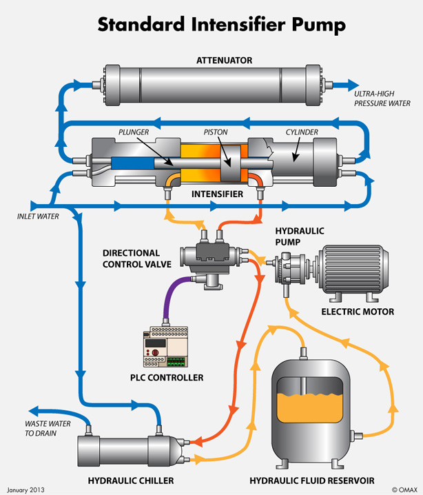
Figure 1: Schematic of a hydraulic intensifier pump.
Figure 1: Schematic of a hydraulic intensifier pump.


Figure 2: Schematic of a crankshaft-driven triplex pump.
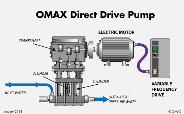
Figure 2: Schematic of a crankshaft-driven triplex pump.
All waterjet cutting systems, regardless of brand or application, have one thing in common, an ultra-high-pressure water pump.
The hydraulic intensifier pump:
Figure 1 shows a schematic drawing of a traditional hydraulic intensifier pump. An electric motor drives a hydraulic pump, which pumps hydraulic fluid at a controlled pressure (generally in the range of 3,000 psi) through a control valve and into the intensifier cylinder.
The hydraulic pressure operates on a relatively large-diameter hydraulic piston to generate a high force on a relatively small-diameter water plunger. This plunger pressurizes the water that it's acting on to a pressure that is proportional to the relative cross-sectional areas of the large piston and the small plunger. For example, if 3,000 psi hydraulic fluid acts on a large piston whose area is 20 square in., and if that piston pushes on a plunger with an area of only 1 square in., the water that is pushed on by the plunger will be pressurized to 60,000 psi (3,000 x 20/1).
The intensifier cylinder is a double-acting cylinder where hydraulic fluid is introduced into one side and then into the other. The hydraulic piston alternately pressurizes the water acted on by the small-diameter plungers at each end of the intensifier assembly.
A series of check valves allows low-pressure water to enter the plunger cylinder as the plunger retracts and then directs the pressurized water into the outlet manifold as the plunger moves into its compression stroke. The back and forth action of the intensifier piston produces a pulsating flow of water at very high pressure.
To help make the flow of water more uniform (thus resulting in a smoother cut), the intensifier pump is equipped with an “attenuator” cylinder, which acts as a high-pressure surge vessel. The use of this attenuator reduces pressure fluctuation to a few thousand psi per stroke.
It's relatively simple to change the design operating water pressure of an intensifier. By simply reducing the cross-sectional area of the water plunger from 1 square in. to 0.67 square in. in the hypothetical example above, the area ratio changes from 20:1 to 30:1, and the water output pressure increases from 60,000 psi to 90,000 psi.
However, it's important to note that the volume flow rate is proportionally reduced because of the reduced displacement per stroke of the smaller diameter plunger. Since the actual power of the output water stream is directly proportional to pressure times volume flow rate, there is no change in the net power of the output water stream. The increase in pressure is offset by the proportional decrease in volume flow rate. Thus, the maximum power output of the pump remains equal to the power of the motor times the operating efficiency of the pump, regardless of operating pressure.
Because of friction losses inherent in any hydraulic system, the hydraulic intensifier is a relatively inefficient pump. Generally, only about 60 percent of the electric power supplied to the drive motor is actually converted into a stream of pressurized water. The other 40 percent is wasted as heat.
Despite this drawback, early ultra-high pressure cutting systems exclusively utilized hydraulic intensifier pumps. This was because the intensifier has a relatively low stroke rate — on the order of one stroke per second or less. That low stroke rate was the key to survival for the high-pressure plunger seals available back in those days, and meant that seal replacement costs could be kept to a commercially acceptable level. Low operating efficiency was simply the price to be paid for acceptable seal life on an intensifier pump.
The crankshaft-driven direct-drive pump
Crankshaft-driven pumps have been in existence literally for centuries. They use a simple mechanical crankshaft to move a piston or plunger back and forth in a cylinder. Check valves allow low-pressure water to enter the cylinder as the plunger retracts and then exit the cylinder into the outlet manifold as the plunger advances into the cylinder and pressurizes the water.
Figure 2 shows a schematic drawing of a typical 3-cylinder triplex crankshaft pump used for abrasive waterjet cutting. By using three plungers operating 120 degrees out of phase, it's possible to generate a very uniform pressure output and eliminate the need for an attenuator.
Crankshaft pumps are inherently more efficient than intensifier pumps because they don't require a power-robbing hydraulic system. The crankshaft drive is a purely mechanical direct-drive system with minimal friction losses; therefore, efficiencies are typically between 85 and 90 percent. This means that 85 percent or more of the electric power supplied to the drive motor can actually be delivered to the cutting nozzle.
However, crankshaft pumps were not used in ultra-high pressure cutting applications in the early days. This was because the typical crankshaft pump operated at more strokes per minute than an intensifier pump and caused unacceptably short life in the seals and check valves that were available at that time. Thus, crankshaft-driven triplex pumps were generally used for high-pressure cleaning and surface preparation applications in the range of 30,000 psi.
However, ongoing improvements in seal designs and materials, and the wide availability and reduced cost of ceramic-valve components now make it possible to operate a crankshaft pump in the 60,000 psi range with long maintenance intervals and excellent reliability.
As an example, the latest EnduroMAX® crankshaft-driven direct-drive pump from OMAX® Corporation has a recommended seal maintenance interval of 1,000 hours for continuous operation at 55,000 psi, which compares favorably with the maintenance experience of intensifier pumps.
Why more fabricating shops are using crankshaft pumps
Most importantly, their higher efficiency means that, for a given size drive motor, they can provide faster cutting and improved productivity.
In the past, potential end users have expressed concern that crankshaft-driven pumps are generally limited to an operating range around 60,000 psi, while hydraulic intensifier pumps are now available in the 90,000 psi range. Users feared that they would sacrifice cutting speed if they used a crankshaft-driven pump. However, head-to-head testing and user experience has shown that such a concern is unfounded.
The reason goes back to the fundamental physics of abrasive waterjet (AWJ) cutting. In AWJ cutting, the abrasive does the cutting, not the water. The water stream only serves to entrain and accelerate the abrasive particles into a coherent abrasive stream.
Maximum cutting speed is determined by the power of the abrasive stream, which is proportional to the power of the water stream, not its pressure. That power is limited by the power of the drive motor and the efficiency of the pump. The higher efficiency of a crankshaft-driven pump means that more of the power of the motor actually gets to the nozzle and the abrasive stream.
The net effect is that a high-efficiency crankshaft-driven pump operating at 60,000 psi can deliver more cutting power than a low-efficiency hydraulic intensifier pump operating at 90,000 psi when both pumps have the same size motor.
As an additional benefit, operation at 60,000 psi puts significantly less stress on high-pressure components such as tubing, fittings and valves, resulting in lower cost and more reliable operation of the overall system.
The end result is less unscheduled downtime and lower overall operating costs with no penalty in production rates. That is the real bottom line to a fabricating shop, and that is why more and more shops are choosing high-efficiency direct-drive pumps at 60,000 psi over low-efficiency hydraulic intensifiers at 90,000 psi.